CHIHAI GM12-15BY Bare-Terminal Geared Stepper Motor, 4.4/10mm Shaft
CHIHAI GM12-15BY Bare-Terminal Geared Stepper Motor, 4.4/10mm Shaft
CHIHAI MOTOR
পিকআপের উপলভ্যতা লোড করা যায়নি


The CHIHAI MOTOR CHS-GM 12-15BY is a miniature geared stepper motor with exposed solder terminals, metal gears and a 3mm D-shaft. Select the actual package, reduction ratio and available 4.4mm or 10mm shaft length. This listing uses the 30ohm winding reference and does not include prewired motor leads.
- Two-phase, four-wire permanent-magnet stepper construction.
- Nine actual reduction ratios and two shaft-length families; only available combinations are offered.
- Compact 15mm motor body and metal gearbox.
- Optional new-driver or PLC-control-driver packages, with or without pictured enclosure.
| Model | CHIHAI MOTOR CHS-GM 12-15BY |
| Construction | Permanent-magnet two-phase, four-wire geared stepper with metal gears and exposed solder terminals |
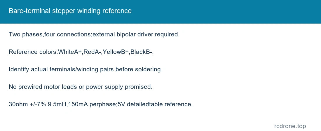
| Winding reference | DC 5V in detailed L 6219 test table; 30ohm ±7% per phase, 9.5mH per phase, 150mA per phase |
| Supply / driver | Suitable bipolar stepper driver required; 5–12V series drive/test references do not mean direct DC rotation or unrestricted winding voltage |
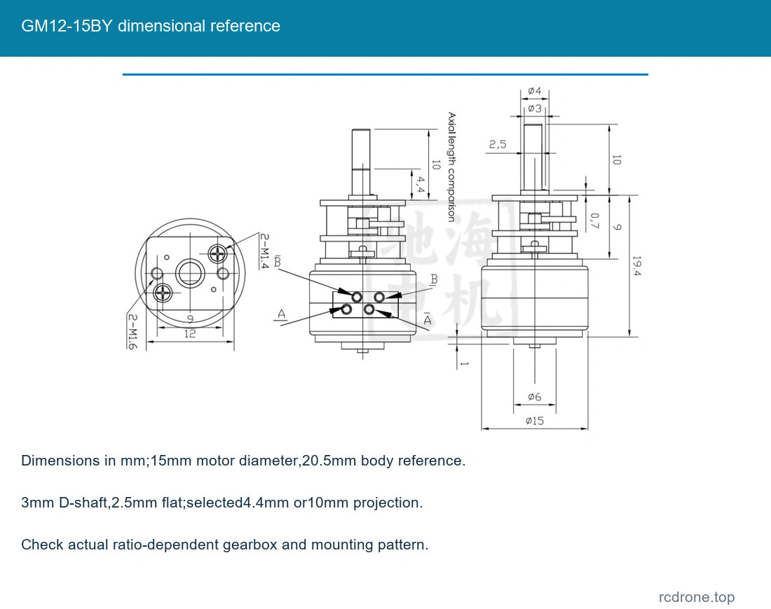
| Size | Approximately 15mm motor diameter; 20.5mm body reference excluding output shaft; assembly varies with ratio |
| Shaft | 3mm D-shaft; 4.4mm or 10mm projection as selected; 2.5mm flat reference |
| Mass | Approximately 13g motor, excluding accessories and shipping packing |
| Ratio | Nine actual nominal ratios 10: 1–380: 1; exact ratios differ slightly |
| Motor step angle | 18degrees before gearbox; output angle follows actual reduction |
| Winding / colors | Reference lead mapping WhiteA+, RedA−, YellowB+, BlackB−; bare motor requires user-supplied wiring and actual terminal confirmation |
| Inclusions | One selected motor plus only the board/enclosure named in selected package; no prewired motor leads or supply promised |
| Frequency headings | Starting> 1200pps, response> 900pps as labeled test references; actual operation depends on driver, load and acceleration |
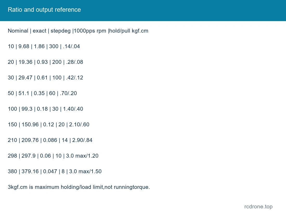
| Nominal | exact ratio | output step degrees |1000pps rpm |holding /pull-out kgf·cm | 10: 1 | 9.68 | 1.86 | 300 | .14 / .04 |
| Nominal | exact ratio | output step degrees |1000pps rpm |holding /pull-out kgf·cm | 20: 1 | 19.36 | 0.93 | 200 | .28 / .08 |
| Nominal | exact ratio | output step degrees |1000pps rpm |holding /pull-out kgf·cm | 30: 1 | 29.47 | 0.61 | 100 | .42 / .12 |
| Nominal | exact ratio | output step degrees |1000pps rpm |holding /pull-out kgf·cm | 50: 1 | 51.1 | 0.35 | 60 | .70 / .20 |
| Nominal | exact ratio | output step degrees |1000pps rpm |holding /pull-out kgf·cm | 100: 1 | 99.3 | 0.18 | 30 | 1.40 / .40 |
| Nominal | exact ratio | output step degrees |1000pps rpm |holding /pull-out kgf·cm | 150: 1 | 150.96 | 0.12 | 20 | 2.10 / .60 |
| Nominal | exact ratio | output step degrees |1000pps rpm |holding /pull-out kgf·cm | 210: 1 | 209.76 | 0.086 | 14 | 2.90 / .84 |
| Nominal | exact ratio | output step degrees |1000pps rpm |holding /pull-out kgf·cm | 298: 1 | 297.9 | 0.06 | 10 | 3.0 max / 1.20 |
| Nominal | exact ratio | output step degrees |1000pps rpm |holding /pull-out kgf·cm | 380: 1 | 379.16 | 0.047 | 8 | 3.0 max / 1.50 |
The output-speed row is an approximate 1000pps test reference using nominal ratio labels. Holding torque is measured at standstill; pull-out torque is a separate rotating reference.3kgf·cm is the maximum permitted holding/load limit for the higher ratios, not a continuous-output rating. Do not force or stall the gearbox.
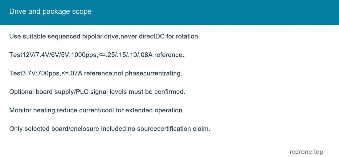
| 12V test | 1000pps reference,≤0.25A suggested drive-current reading |
| 7.4V test | 1000pps reference,≤0.15A |
| 6V test | 1000pps reference,≤0.10A |
| 5V test | 1000pps reference,≤0.08A |
| 3.7V test | 700pps reference,≤0.07A |
These voltage-dependent drive-test readings are distinct from the 150mA phase specification and 5V winding table. Use a suitable bipolar driver with correct current control and check motor heating during extended tests. Reduce current or provide cooling if temperature rises excessively. The optional board input rating and PLC signal levels must be confirmed on the actual supplied board before wiring; they are not specified here.
Reference lead colors identify WhiteA+ and RedA− as phaseA, YellowB+ and BlackB− as phaseB. The bare motor has exposed terminals; identify winding pairs and actual terminal orientation before soldering user-supplied leads. A stepper requires sequenced excitation from a driver and will not rotate continuously from a direct DC connection. Avoid overheating terminals and insulate connections.
Fit the selected 4.4mm or 10mm shaft projection to the mechanism. Support external loads, check the dimensioned mounting pattern and avoid excessive side load, gear overload or abrupt acceleration. Optional driver and enclosure styles are shown in their actual package photos; no undocumented PLC compatibility or input voltage is implied.
Motor Only: one selected-ratio/shaft motor. New Driver Board or PLC Driver packages add the pictured respective board. Enclosed packages add the matching housing. Power supply, prewired motor lead, coupling and bracket are not included unless expressly identified in the package.
Small positioning mechanisms, camera prototypes, robotic joints, instruments and compact automation projects using a compatible stepper controller.
Only the stocked source combinations are offered; short-shaft 10: 1, 20: 1, 30: 1 and 210: 1 configurations are unavailable in this saved range.
No.Check the actual supplied board documentation and pin labels before connecting a PLC or power supply.
Visual Details