


JGB37-520 ডিসি গিয়ার মোটর হ্যাল এনকোডারসহ, ১২ভি/২৪ভি, ৭–৯৬০ আরপিএম, ৩৭মিমি মেটাল গিয়ারবক্স এবং ৬মিমি ডি-শ্যাফ্ট
JGB37-520 ডিসি গিয়ার মোটর হ্যাল এনকোডারসহ, ১২ভি/২৪ভি, ৭–৯৬০ আরপিএম, ৩৭মিমি মেটাল গিয়ারবক্স এবং ৬মিমি ডি-শ্যাফ্ট
Jiali Motor
পিকআপের উপলভ্যতা লোড করা যায়নি


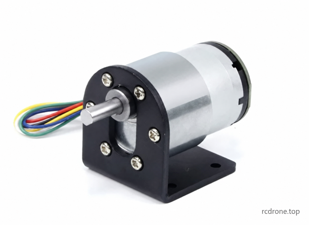
JGB37-520 ব্রাশড DC গিয়ার মোটর হাল এনকোডার সহ
JGB37-520 একটি কমপ্যাক্ট ব্রাশড DC গিয়ার মোটর যা একটি A/B ইনক্রিমেন্টাল হল এনকোডার, একটি ধাতব রিডাকশন গিয়ারবক্স, একটি 6mm D-আকৃতির আউটপুট শাফট এবং বিপরীত রোটেশন সহ। ১২V বা ২৪V মোটর, প্রয়োজনীয় নো-লোড আউটপুট স্পিড এবং রোবোটিক্স, ছোট যন্ত্রপাতি এবং ইলেকট্রনিক প্রকল্পের জন্য মোটর-শুধু বা অ্যাক্সেসরি প্যাকেজ নির্বাচন করুন।
নির্বাচনযোগ্য স্পিডগুলি হল ৭, ১২, ২২, ৩৫, ৪৫, ৬৬, ১০৭, ২০০, ৩১৯, ৬০০ এবং ৯৬০ RPM। এই বিকল্পগুলি সরবরাহকারীর 6000RPM মোটর-বিফোর-রিডাকশন সিরিজের সাথে মেলে। আউটপুট RPM লোড ছাড়া পরিমাপ করা হয়; লোডের অধীনে স্পিড কমে যায়। একটি ফটোগ্রাফে প্রদর্শিত একটি ব্র্যাকেট শুধুমাত্র তখনই অন্তর্ভুক্ত হয় যখন নির্বাচিত প্যাকেজ একটি ব্র্যাকেট নামকরণ করে।
নির্মাণ এবং স্পিড কন্ট্রোল
- একাধিক স্তরের ব্যবস্থায় ধাতব রিডাকশন গিয়ার, তামার প্যাঁচ, স্থায়ী-চুম্বক মোটর এবং কার্বন ব্রাশ।
- একটি সামঞ্জস্যপূর্ণ বাইরের ব্রাশড-ডিসি কন্ট্রোলারের সাথে PWM গতি নিয়ন্ত্রণ সম্ভব। একটি কন্ট্রোলার শুধুমাত্র নির্দিষ্ট প্যাকেজগুলিতে অন্তর্ভুক্ত রয়েছে।
- ঘূর্ণন বিপরীত করতে শুধুমাত্র লাল এবং সাদা মোটর পাওয়ার লিডগুলি পরিবর্তন করুন। এনকোডার এবং কন্ট্রোলারের সরবরাহের ধ্রুবক সঠিক রাখুন; দিক পরিবর্তনের আগে মোটর বন্ধ করুন।
- গিয়ার অনুপাত গতি/টর্কের বিনিময় নির্ধারণ করে। বৈদ্যুতিকভাবে গতি কমানো একই টর্ক বৃদ্ধি প্রদান করে না যেমন একটি উচ্চতর হ্রাস অনুপাত নির্বাচন করা।
যান্ত্রিক স্পেসিফিকেশন
| প্যারামিটার | স্পেসিফিকেশন |
|---|---|
| ব্র্যান্ড / মডেল | জিয়ালি মোটর / JGB37-520 |
| মোটর টাইপ | ব্রাশড ডিসি গিয়ার মোটর A/B ইনক্রিমেন্টাল ম্যাগনেটিক হল এনকোডার সহ |
| রেটেড সাপ্লাই | 12V DC অথবা 24V DC, নির্বাচিত ভেরিয়েন্ট অনুযায়ী |
| গিয়ারবক্সের ব্যাস | 37mm |
| মোটর বডির ব্যাস / সেকশন দৈর্ঘ্য | 32mm / 22mm |
| গিয়ারবক্সের দৈর্ঘ্য L | 19–29mm, রিডাকশন রেশিওর উপর নির্ভর করে |
| আউটপুট শ্যাফট | 6mm ব্যাস, 15.5mm প্রজেকশন; 12mm ফ্ল্যাট দৈর্ঘ্য; 5.5mm সমতল |
| শাফের ব্যাস সহনশীলতা | −0.03 / −0.05mm, অঙ্কনে চিহ্নিত হিসাবে |
| লোকেটিং বশ | 12mm ব্যাস × 6mm উচ্চতা |
| মাউন্টিং | একটি 31mm পিচ বৃত্তে ছয়টি M3 থ্রেডেড গর্ত; অঙ্কন 3.5mm গভীরতা নির্দিষ্ট করে, ফটোগ্রাফ 4mm নির্দিষ্ট করে। প্রকৃত মোটরে স্ক্রু জড়িত হওয়া নিশ্চিত করুন। |
| এনকোডার এবং কেবল | 32mm এনকোডার ব্যাস; পেছনের সমাবেশ প্রকল্প 11.75mm; PH2.0 ছয়-পিন কেবল প্রায় 144mm লম্বা |
| শাফের অফসেট | মোটরের কেন্দ্ররেখা থেকে 7mm |
| সরবরাহকারী রেফারেন্সে হ্রাস অনুপাত | 6.২৫:১–৮১০:১; প্রতিটি রেফারেন্স অনুপাত নির্বাচনযোগ্য নয় |
| মোটর-শুধুমাত্র ওজন | অনুপাত অনুযায়ী প্রায় ১৪৪–১৭০গ্রাম; ওভারভিউতে প্রায় ১৭০গ্রাম উল্লেখ করা হয়েছে |
| সরবরাহকারী ওভারভিউ রেটিং | ২.৪–১০.৮W এবং ০.১৫–০.৬৫A চিত্রিত সিরিজ জুড়ে; নিচের সিরিজ-নির্দিষ্ট টেবিলগুলি ব্যবহার করুন |
| সরবরাহকারী অপারেটিং দাবি | −১০°C থেকে ৭০°C; ওভারভিউ ২৪-ঘণ্টার ব্যবহারের তালিকা করে। প্রকৃত ডিউটি উপযোগিতা লোড এবং কুলিংয়ের উপর নির্ভর করে। |
| শব্দ | সরবরাহকারী প্রায় ৫৫dB উল্লেখ করে, যা গতি এবং লোডের সাথে পরিবর্তিত হয়; পরিমাপের শর্তাবলী নির্দিষ্ট করা হয়নি |
আকারগুলি সরবরাহকারীর রেফারেন্স পরিমাপ এবং পরিবর্তিত হতে পারে। মোটরের চেহারা এবং উপাদানগুলি সংস্করণের মধ্যে ভিন্ন হতে পারে।এনকোডার ফিডব্যাক সিগন্যাল সরবরাহ করে; ক্লোজড-লুপ কন্ট্রোলের জন্য একটি উপযুক্ত বাইরের কন্ট্রোলার প্রয়োজন। এনকোডার তাপমাত্রার দাবি সম্পূর্ণ মোটর অপারেটিং পরিসরকে প্রসারিত করে না।
6000RPM মোটর সিরিজ — পারফরম্যান্স রেফারেন্স
এই সিরিজটি নির্বাচনী গতি পরিবারের সাথে মেলে। টেবিলগুলোতে সরবরাহকারীর অ-নির্বাচনযোগ্য রেফারেন্স গতিগুলি (৮৫, ২৮, ১৫ এবং ৯.৫ RPM) সম্পূর্ণতার জন্য রাখা হয়েছে; এগুলি অতিরিক্ত ক্রয় বিকল্প তৈরি করে না। মানগুলি সরবরাহকারীর তথ্য, স্বাধীন পরীক্ষার ফলাফল নয়। টর্ক হল kgf·cm, লিফটিং ক্যাপাসিটির কিলোগ্রাম নয়।
১২V — 6000RPM রিডাকশনের আগে
| অনুপাত | গিয়ারবক্স L (মিমি) | নো-লোড RPM | নো-লোড কারেন্ট (এ) | লোডেড RPM | সর্বাধিক টর্ক।কার্যকারিতা (kgf·cm) | লোডেড কারেন্ট (A) | শক্তি (W) | স্টল টর্ক (kgf·cm) | স্টল কারেন্ট (A) | শুরু করার ভোল্টেজ (V) | মোটর ওজন (g) |
|---|---|---|---|---|---|---|---|---|---|---|---|
| 6.25 | 19 | 960 | 0.1 | 672 | 0.17 | 0.2 | 2.4 | 0.6 | 1.2 | 1.5 | 144 |
| 10 | 19 | 600 | 0.1 | 480 | 0.28 | 0.2 | 2.4 | 1.1 | 1.2 | 1.5 | 144 |
| 18.8 | 22 | 319 | 0.1 | 255 | 0.48 | 0.2 | 2.4 | 1.9 | 1.2 | 1.5 | 150 |
| 30 | 22 | 200 | 0.1 | 160 | 0.75 | 0.2 | 2.4 | 3 | 1.2 | 1.5 | 150 |
| 56 | 24 | 107 | 0.1 | 85 | 1.2 | 0.2 | 2.4 | 4.8 | 1.2 | 1.5 | 158 |
| 70 | 24 | 85 | 0.1 | 68 | 1.5 | 0.2 | 2.4 | 6 | 1.2 | 1.5 | 158 |
| 90 | 24 | 66 | 0.1 | 52 | 2 | 0.2 | 2.4 | 8 | 1.2 | 1.5 | 158 |
| 131 | 26.5 | 45 | 0.1 | 36 | 2.7 | 0.2 | 2.4 | 10.8 | 1.2 | 1.5 | 164 |
| 169 | 26.5 | 35 | 0.1 | 28 | 3.4 | 0.3 | 3.6 | 13.6 | 1.2 | 1.5 | 164 |
| 210 | 26.5 | 28 | 0.1 | 22 | 4.3 | 0.3 | 3.6 | 17.2 | 1.2 | 1.5 | 164 |
| 270 | 26.5 | 22 | 0.1 | 18 | 5.5 | 0.3 | 3.6 | 22 | 1.2 | 1.5 | 164 |
| 394 | 29 | 15 | 0.1 | 12 | 7.3 | 0.3 | 3.6 | 29.2 | 1.2 | 1.5 | 170 |
| 506 | 29 | 12 | 0.1 | 9.4 | 9.1 | 0.3 | 3.6 | 36.4 | 1.2 | 1.5 | 170 |
| 630 | 29 | 9.5 | 0.1 | 7.6 | 11.6 | 0.3 | 3.6 | 46.4 | 1.2 | 1.5 | 170 |
| 810 | 29 | 7 | 0.1 | 5.6 | 15 | 0.3 | 3.6 | 80 | 1.2 | 1.5 | 170 |
24V — 6000RPM পূর্বে হ্রাস
| অনুপাত | গিয়ারবক্স L (মিমি) | নো-লোড RPM | নো-লোড কারেন্ট (এ) | লোডেড RPM | সর্বাধিক টর্ককার্যকারিতা (kgf·cm) | লোডেড কারেন্ট (A) | শক্তি (W) | স্টল টর্ক (kgf·cm) | স্টল কারেন্ট (A) | শুরু করার ভোল্টেজ (V) | মোটর ওজন (g) |
|---|---|---|---|---|---|---|---|---|---|---|---|
| 6.25 | 19 | 960 | 0.05 | 672 | 0.17 | 0.15 | 3.6 | 0.6 | 0.6 | 2 | 144 |
| 10 | 19 | 600 | 0.05 | 480 | 0.28 | 0.15 | 3.6 | 1.1 | 0.6 | 2 | 144 |
| 18.8 | 22 | 319 | 0.05 | 255 | 0.48 | 0.15 | 3.6 | 1.9 | 0.6 | 2 | 150 |
| 30 | 22 | 200 | 0.05 | 160 | 0.75 | 0.15 | 3.6 | 3 | 0.6 | 2 | 150 |
| 56 | 24 | 107 | 0.05 | 85 | 1.2 | 0.15 | 3.6 | 4.8 | 0.6 | 2 | 158 |
| 70 | 24 | 85 | 0.05 | 68 | 1.5 | 0.15 | 3.6 | 6 | 0.6 | 2 | 158 |
| 90 | 24 | 66 | 0.05 | 52 | 2 | 0.15 | 3.6 | 8 | 0.6 | 2 | 158 |
| 131 | 26.5 | 45 | 0.05 | 36 | 2.7 | 0.15 | 3.6 | 10.8 | 0.6 | 2 | 164 |
| 169 | 26.5 | 35 | 0.05 | 28 | 3.4 | 0.15 | 3.6 | 13.6 | 0.6 | 2 | 164 |
| 210 | 26.5 | 28 | 0.05 | 22 | 4.3 | 0.15 | 3.6 | 17.2 | 0.6 | 2 | 164 |
| 270 | 26.5 | 22 | 0.05 | 18 | 5.5 | 0.15 | 3.6 | 22 | 0.6 | 2 | 164 |
| 394 | 29 | 15 | 0.05 | 12 | 7.3 | 0.15 | 3.6 | 29.2 | 0.6 | 2 | 170 |
| 506 | 29 | 12 | 0.05 | 9.4 | 9.1 | 0.15 | 3.6 | 36.4 | 0.6 | 2 | 170 |
| 630 | 29 | 9.5 | 0.05 | 7.6 | 11.6 | 0.15 | 3.6 | 46.4 | 0.6 | 2 | 170 |
| 810 | 29 | 7 | 0.05 | 5.6 | 15 | 0.15 | 3.6 | 80 | 0.6 | 2 | 170 |
10000RPM মোটর সিরিজ — অতিরিক্ত সরবরাহকারী রেফারেন্স মাত্র
সরবরাহিত ছবিতে নিম্নলিখিত উচ্চ-গতি মোটর সিরিজও অন্তর্ভুক্ত রয়েছে। এটি রেফারেন্স তথ্য মাত্র: এটি এই তালিকায় আলাদাভাবে নির্বাচিত সিরিজ নয়।এই সংখ্যাগুলি কেনা 6000RPM-সিরিজের ভেরিয়েন্টে প্রয়োগ করবেন না, এমনকি যেখানে আউটপুট RPM ওভারল্যাপ করে।
12V — 10000RPM রিডাকশনের আগে (শুধুমাত্র রেফারেন্স)
| অনুপাত | গিয়ারবক্স L (মিমি) | নো-লোড RPM | নো-লোড কারেন্ট (এ) | লোডেড RPM | সর্বাধিক দক্ষতায় টর্ক (kgf·cm) | লোডেড কারেন্ট (এ) | শক্তি (W) | স্টল টর্ক (kgf·cm) | স্টল কারেন্ট (এ) | শুরু করার ভোল্টেজ (V) | মোটর ওজন (গ্রাম) |
|---|---|---|---|---|---|---|---|---|---|---|---|
| 6.25 | 19 | 1600 | 0.15 | 1200 | 0.23 | 0.65 | 7.8 | 0.9 | 2.4 | 1.5 | 144 |
| 10 | 19 | 1000 | 0.15 | 770 | 0.4 | 0.65 | 7.8 | 1.6 | 2.4 | 1.5 | 144 |
| 18.8 | 22 | 530 | 0.15 | 407 | 0.67 | 0.65 | 7.8 | 2.6 | 2.4 | 1.5 | 150 |
| 30 | 22 | 333 | 0.15 | 250 | 1 | 0.65 | 7.8 | 4 | 2.4 | 1.5 | 150 |
| 56 | 24 | 178 | 0.15 | 140 | 1.8 | 0.65 | 7.8 | 7.2 | 2.4 | 1.5 | 158 |
| 70 | 24 | 142 | 0.15 | 110 | 2.2 | 0.65 | 7.8 | 8.8 | 2.4 | 1.5 | 158 |
| 90 | 24 | 110 | 0.15 | 85 | 3 | 0.65 | 7.8 | 12 | 2.4 | 1.5 | 158 |
| 131 | 26.5 | 76 | 0.15 | 58 | 3.9 | 0.65 | 7.8 | 15.6 | 2.4 | 1.5 | 164 |
| 169 | 26.5 | 60 | 0.15 | 46 | 5 | 0.65 | 7.8 | 20 | 2.4 | 1.5 | 164 |
| 210 | 26.5 | 47 | 0.15 | 36 | 6 | 0.65 | 7.8 | 24 | 2.4 | 1.5 | 164 |
| 270 | 26.5 | 37 | 0.15 | 28 | 8 | 0.65 | 7.8 | 32 | 2.4 | 1.5 | 164 |
| 394 | 29 | 25 | 0.15 | 19.5 | 10.4 | 0.65 | 7.8 | 41.6 | 2.4 | 1.5 | 170 |
| 506 | 29 | 20 | 0.15 | 15 | 13.6 | 0.65 | 7.8 | 54.4 | 2.4 | 1.5 | 170 |
| 630 | 29 | 15.8 | 0.15 | 12 | 16.6 | 0.65 | 7.8 | 66.4 | 2.4 | 1.5 | 170 |
| 810 | 29 | 12 | 0.15 | 9 | 21 | 0.65 | 7.8 | 93 | 2.4 | 1.5 | 170 |
6V / 5000RPM সিরিজ — অতিরিক্ত সরবরাহকারী রেফারেন্স শুধুমাত্র
এই উৎস টেবিলটি রেফারেন্সের জন্য সংরক্ষিত এবং এই তালিকায় একটি নির্বাচনী ভোল্টেজ বা সিরিজ নয়।
| অনুপাত | গিয়ারবক্স L (মিমি) | নো-লোড RPM | নো-লোড কারেন্ট (এ) | লোডেড RPM | সর্বাধিক দক্ষতায় টর্ক (কেজিএফ·সেমি) | লোডেড কারেন্ট (এ) | শক্তি (W) | স্টল টর্ক (কেজিএফ·সেমি) | স্টল কারেন্ট (এ) | শুরু করার ভোল্টেজ (V) | মোটর ওজন (গ্রাম) |
|---|---|---|---|---|---|---|---|---|---|---|---|
| 6.25 | 19 | 800 | 0.08 | 600 | 0.11 | 0.33 | 1.98 | 0.45 | 1.2 | 1.5 | 144 |
| 10 | 19 | 500 | 0.08 | 385 | 0.2 | 0.33 | 1.98 | 0.8 | 1.2 | 1.5 | 144 |
| 18.8 | 22 | 265 | 0.08 | 203.5 | 0.33 | 0.33 | 1.98 | 1.3 | 1.2 | 1.5 | 150 |
| 30 | 22 | 166.5 | 0.08 | 125 | 0.5 | 0.33 | 1.98 | 2 | 1.2 | 1.5 | 150 |
| 56 | 24 | 89 | 0.08 | 70 | 0.9 | 0.33 | 1.98 | 3.6 | 1.2 | 1.5 | 158 |
| 70 | 24 | 71 | 0.08 | 55 | 1.1 | 0.33 | 1.98 | 4.4 | 1.2 | 1.5 | 158 |
| 90 | 24 | 55 | 0.08 | 42.5 | 1.5 | 0.33 | 1.98 | 6 | 1.2 | 1.5 | 158 |
| 131 | 26.5 | 38 | 0.08 | 29 | 1.95 | 0.33 | 1.98 | 7.8 | 1.2 | 1.5 | 164 |
| 169 | 26.5 | 30 | 0.08 | 23 | 2.5 | 0.33 | 1.98 | 10 | 1.2 | 1.5 | 164 |
| 210 | 26.5 | 23.5 | 0.08 | 18 | 3 | 0.33 | 1.98 | 12 | 1.2 | 1.5 | 164 |
| 270 | 26.5 | 18.5 | 0.08 | 14 | 4 | 0.33 | 1.98 | 16 | 1.2 | 1.5 | 164 |
| 394 | 29 | 12.5 | 0.08 | 9.7 | 5.2 | 0.33 | 1.98 | 20.8 | 1.2 | 1.5 | 170 |
| 506 | 29 | 10 | 0.08 | 7.5 | 6.8 | 0.33 | 1.98 | 27.2 | 1.2 | 1.5 | 170 |
| 630 | 29 | 7.9 | 0.08 | 6 | 8.3 | 0.33 | 1.98 | 33.2 | 1.2 | 1.5 | 170 |
| 810 | 29 | 6 | 0.08 | 4.5 | 10.5 | 0.33 | 1.98 | 46.5 | 1.2 | 1.5 | 170 |
হল এনকোডার স্পেসিফিকেশন এবং ওয়্যারিং
মোটর সরবরাহ এবং এনকোডার সরবরাহ আলাদা সার্কিট। অপশন অনুযায়ী মোটরের জন্য 12V বা 24V ব্যবহার করুন, এবং এনকোডারের জন্য শুধুমাত্র 3.3–5V DC ব্যবহার করুন। কখনো এনকোডার বা সিগন্যাল তারে মোটর ভোল্টেজ প্রয়োগ করবেন না।
| এনকোডার প্যারামিটার | স্পেসিফিকেশন |
|---|---|
| প্রকার | A/B দুই-চ্যানেল ইনক্রিমেন্টাল ম্যাগনেটিক হল এনকোডার |
| বেস রেজোলিউশন | 11 পালস প্রতি মোটর বিপ্লব (11PPR) |
| আউটপুট শ্যাফট পালস রেফারেন্স | 11 × গিয়ার অনুপাত কোয়াড্রেচার এজ গুণনের আগে; প্রকৃত গণনা ডিকোডিং পদ্ধতির উপর নির্ভর করে |
| এনকোডার সাপ্লাই | 3.3–5V DC |
| আউটপুট | A/B বর্গ তরঙ্গ, স্ট্যান্ডার্ড; সোর্স সাইন-ওয়েভ কাস্টম সংস্করণ এখানে একটি নির্বাচনী কনফিগারেশন নয় |
| ইন্টারফেস | PH2.0-6PIN সরবরাহিত কেবল সহ |
| সংকেত সার্কিট | নির্মিত পুল-আপ এবং কন্ডিশনিং রেজিস্টর; আপনার কন্ট্রোলারের সাথে লজিক-লেভেল সামঞ্জস্য যাচাই করুন |
| প্রতিক্রিয়া ফ্রিকোয়েন্সি | 100kHz, সরবরাহকারী স্পেসিফিকেশন |
| চৌম্বক রিং | 22 পোল / 11 পোল জোড় |
| সরবরাহকারী এনকোডার তাপমাত্রা | −40°C থেকে 120°C; এনকোডার স্পেসিফিকেশনের জন্য প্রযোজ্য, সম্পূর্ণ মোটরের জন্য নয় |
| তারের রঙ | সংযোগ |
|---|---|
| লাল | মোটর পাওয়ার +; মোটর বিপরীত করতে শুধুমাত্র সাদা সঙ্গে পরিবর্তন করুন |
| সাদা | মোটর পাওয়ার −; মোটর বিপরীত করতে শুধুমাত্র লাল সঙ্গে পরিবর্তন করুন |
| কালো | এনকোডার সরবরাহ − / GND |
| নীল | এনকোডার সরবরাহ +, 3.3–5V DC |
| হলুদ | এনকোডার সিগন্যাল চ্যানেল |
| সবুজ | এনকোডার সিগন্যাল চ্যানেল |
উৎস হলুদ এবং সবুজকে দুটি সিগন্যাল লাইন হিসেবে চিহ্নিত করে, তাদের A/B ক্রম নির্ধারণ না করে। আপনার অ্যাপ্লিকেশনে চ্যানেল ফেজ পরীক্ষা করুন। কখনো নীল/কালো এনকোডার সরবরাহ বিপরীত করবেন না, এবং কখনো সিগন্যাল লাইনে সরাসরি পাওয়ার সংযোগ করবেন না।
ঐচ্ছিক মাউন্টিং ব্র্যাকেট
চিত্রিত L-ব্র্যাকেটের পুরুত্ব 1.5 মিমি, প্রায় 40 মিমি প্রস্থ, 40 মিমি ভিত্তি এবং 47 মিমি উল্লম্ব। মোটর মাউন্টিং প্যাটার্নটি 31 মিমি পিচ ব্যাসার্ধে চিহ্নিত করা হয়েছে, ছয়টি 3.2 মিমি গর্ত এবং 6.3 মিমি গহ্বর সহ। কেন্দ্রীয় খোলাটি 2 × R6.5 চিহ্নিত করা হয়েছে 14 মিমি কেন্দ্রের ব্যবধান সহ। ভিত্তির অঙ্কনে 24 × 30 মিমি ব্যবধানের চারটি 3.5 মিমি গর্ত এবং 8 মিমি পাশের অফসেট দেখানো হয়েছে; উল্লম্বে 20 মিমি রেফারেন্স মাত্রা অন্তর্ভুক্ত রয়েছে।ব্র্যাকেটটি শুধুমাত্র প্রযোজ্য প্যাকেজের সাথে সরবরাহ করা হয়।
তারের সংযোগ এবং ব্যবহার
নির্বাচিত ভোল্টেজের সাথে মেলে এমন একটি ডিসি মোটর সরবরাহ এবং একটি পৃথক নিয়ন্ত্রিত 3.3–5V এনকোডার সরবরাহ ব্যবহার করুন। যদি একটি PWM মোটর কন্ট্রোলার ব্যবহার করা হয়, তবে এর মোটর আউটপুটটি শুধুমাত্র লাল এবং সাদা মোটর লিডগুলির সাথে সংযুক্ত করুন। এনকোডার পাওয়ার এবং সংকেতগুলিকে মোটর পাওয়ার আউটপুট থেকে আলাদা রাখুন। দিক পরিবর্তনের আগে থামুন এবং পাওয়ার প্রয়োগের আগে প্রতিটি সংযোগ যাচাই করুন।
মোটরটি এর রেটেড-লোড টর্ক দ্বারা নির্বাচন করুন, স্টল টর্ক দ্বারা নয়। অতিরিক্ত লোড, স্টল বা স্টলের কাছাকাছি অপারেট করবেন না: মোটর বা গিয়ার ক্ষতিগ্রস্ত হতে পারে। রেটেড অবস্থার উপরে লোড গতি কমিয়ে দেয়। বৈদ্যুতিক গতি কমানোও উপলব্ধ টর্ক কমাতে পারে। কন্ট্রোলার রেটিং, অ্যাডাপ্টার মেইনস-ইনপুট রেটিং, প্লাগের ধরন এবং অন্তর্ভুক্ত কেবল/কনেক্টরের বিবরণগুলি সরবরাহিত তালিকায় সম্পূর্ণরূপে নির্দিষ্ট করা হয়নি; নির্বাচিত অ্যাক্সেসরির জন্য এই বিবরণগুলি যাচাই করুন।
টর্ক এবং ইউনিট রেফারেন্স
একটি স্থির লোডের জন্য, প্রয়োজনীয় টর্ক কেজি·সেমি লোড কেজি·ফরসা দ্বারা লিভার রেডিয়াস সেমিতে গুণিতক। সরবরাহকারী একটি 10কেজি লোডের উদাহরণ দেয়: 1সেমি রেডিয়াসে 10কেজি·ফরসা·সেমি, অথবা 10সেমি রেডিয়াসে 100কেজি·ফরসা·সেমি। এটি একটি ব্যাখ্যামূলক উদাহরণ, এই মোটরের উত্তোলন রেটিং নয়। ঘর্ষণ, ত্বরণ এবং যন্ত্রের প্রকৃত অপারেটিং লোডের জন্য অনুমতি দিন।
| gf·সেমি | কেজি·ফরসা·সেমি | N·মি | mN·মি | N·সেমি |
|---|---|---|---|---|
| 1 | 0.001 | 9.8e-05 | 0.098 | 0.0098 |
| 1000 | 1 | 0.098 | 98 | 9.8 |
| 10204.08 | 10.204 | 1 | 1000 | 100 |
| 10.2 | 0.01 | 0.001 | 1 | 0.1 |
| 102.04 | 0.102 | 0.01 | 10 | 1 |
প্যাকেজের সামগ্রী
একটি JGB37-520 মোটর হল এনকোডার এবং নির্বাচিত ভোল্টেজ এবং গতির জন্য ছয়-পিন সংযোগ কেবল সহ, প্লাস শুধুমাত্র প্যাকেজ অপশনে নামকৃত আনুষাঙ্গিকগুলি:
- মোটর শুধুমাত্র
- মোটর + ব্র্যাকেট
- মোটর + স্পিড কন্ট্রোলার
- মোটর + পাওয়ার সাপ্লাই
- মোটর + ব্র্যাকেট + স্পিড কন্ট্রোলার
- মোটর + ব্র্যাকেট + পাওয়ার সাপ্লাই
- মোটর + স্পিড কন্ট্রোলার + পাওয়ার সাপ্লাই
- মোটর + ব্র্যাকেট + স্পিড কন্ট্রোলার + পাওয়ার সাপ্লাই
মোটর শুধুমাত্র একটি ব্র্যাকেট, স্পিড কন্ট্রোলার বা পাওয়ার সাপ্লাই অন্তর্ভুক্ত করে না। পণ্য এবং আনুষাঙ্গিকের চিত্রগুলি রেফারেন্স ভিউ।
বিস্তারিত
সরবরাহকারীর চিত্রের ইংরেজি সংস্করণ, ব্যাখ্যা এবং সিরিজ-নির্দিষ্ট রেফারেন্স নোট সহ।
এনকোডার মোটর পর্যালোচনা
JGB37-520 একটি ব্রাশড DC মোটর, ধাতব রিডাকশন গিয়ারবক্স এবং হল এনকোডারকে একত্রিত করে। উপরে ভোল্টেজ, নো-লোড স্পিড এবং অ্যাক্সেসরি প্যাকেজ নির্বাচন করুন।

টর্ক এবং স্পিড নিয়ন্ত্রণ
গিয়ার রিডাকশন স্পিড এবং টর্কের মধ্যে সমঝোতা নির্ধারণ করে। PWM নিয়ন্ত্রণের জন্য একটি উপযুক্ত বাইরের কন্ট্রোলার প্রয়োজন। মোটরের পাওয়ার লিডগুলি বিপরীত করুন, এনকোডার পাওয়ার পোলারিটি অপরিবর্তিত রেখে।

অভ্যন্তরীণ নির্মাণ
সূত্রটি ধাতব গিয়ার, তামার উইন্ডিং, স্থায়ী চুম্বক, কার্বন ব্রাশ এবং পেছনের হল এনকোডার চিত্রিত করে। অভ্যন্তরীণ অংশগুলি উৎপাদন সংস্করণের মধ্যে পরিবর্তিত হতে পারে।

যান্ত্রিক মাত্রা
মাত্রাগুলি মিলিমিটারে। গিয়ারবক্সের দৈর্ঘ্য হ্রাস অনুপাতের উপর নির্ভর করে। অঙ্কনে 3.5 মিমি মাউন্টিং-হোল গভীরতা নির্দিষ্ট করা হয়েছে, যখন নীচের চিত্রিত ফটোগ্রাফ 4 মিমি নির্দিষ্ট করে; প্রকৃত মোটরে স্ক্রু জড়িত হওয়া যাচাই করুন।

ঐচ্ছিক মাউন্টিং ব্র্যাকেট
এই ব্র্যাকেটটি শুধুমাত্র তখনই অন্তর্ভুক্ত করা হয় যখন নির্বাচিত প্যাকেজ একটি ব্র্যাকেটের নাম উল্লেখ করে। এর মাউন্টিং মাত্রাগুলি নীচে দেখানো হয়েছে।

মোটর এবং এনকোডার মাত্রা
এনকোডার সমাবেশ একটি 11.75 মিমি পেছনের অংশ যোগ করে। সরবরাহিত ছয়-পিনের কেবল প্রায় 144 মিমি দীর্ঘ।সংক্ষিপ্ত বিবরণ রেটিং বিভিন্ন উৎস সিরিজ জুড়ে বিস্তৃত; কর্মক্ষমতা টেবিলগুলিতে নির্বাচিত সিরিজের দিকে নির্দেশ করুন।

এনকোডার তারের সংযোগ এবং সংকেত
মোটর পাওয়ার লাল এবং সাদা তার ব্যবহার করে। এনকোডার পাওয়ার নীল (+3.3–5V) এবং কালো (GND); হলুদ এবং সবুজ দুটি এনকোডার সংকেত বহন করে। উৎস এই দুটি রঙের জন্য A/B অর্ডার নির্ধারণ করে না। কখনো 12V/24V মোটর ভোল্টেজ এনকোডার বা সংকেত সংযোগে প্রয়োগ করবেন না।

টর্ক নির্বাচন রেফারেন্স
এই পুলি উদাহরণগুলি টর্ক এবং লিভার ব্যাসার্ধ ব্যাখ্যা করে; এগুলি এই মোটরের জন্য উত্তোলন-ক্ষমতা রেটিং নয়। ঘর্ষণ, ত্বরান্বিত এবং প্রকৃত লোডের জন্য অনুমতি দিন।

6V / 5000RPM সিরিজ — রেফারেন্সের জন্য
এই অতিরিক্ত উৎস টেবিলটি রেফারেন্সের জন্য প্রদান করা হয়েছে। এই তালিকায় এই ভোল্টেজ বা এই মোটর সিরিজটি নির্বাচনের জন্য উপলব্ধ নয়।

12V / 6000RPM সিরিজ
এটি নির্বাচনী ভেরিয়েন্ট দ্বারা ব্যবহৃত 12V স্পিড ফ্যামিলি। উৎসটি 85, 28, 15 এবং 9.5RPM রেফারেন্স স্পিডও তালিকাভুক্ত করে যা ক্রয়ের বিকল্প হিসেবে উপলব্ধ নয়। স্টল টর্ক একটি ধারাবাহিক অপারেটিং রেটিং নয়।

24V / 6000RPM সিরিজ
এটি নির্বাচনী ভেরিয়েন্ট দ্বারা ব্যবহৃত 24V স্পিড ফ্যামিলি। সমস্ত মান সরবরাহকারী রেফারেন্স ডেটা। যান্ত্রিক নকশা করার সময় নির্বাচিত ভোল্টেজ এবং রেটেড-লোড সংখ্যা ব্যবহার করুন।

12V / 10000RPM সিরিজ — শুধুমাত্র রেফারেন্স
এই উচ্চ-গতি উৎস সিরিজ এখানে একটি নির্বাচনী মোটর সিরিজ নয়। তালিকাভুক্ত 6000RPM-সিরিজ মোটরে এর রেটিং প্রয়োগ করবেন না, এমনকি যখন আউটপুট গতি ওভারল্যাপ করে।

