Kunwei KWR75Ex Explosion-Proof Six-Axis Force/Torque Sensor, 75 mm, for Robotic Arms
Kunwei KWR75Ex Explosion-Proof Six-Axis Force/Torque Sensor, 75 mm, for Robotic Arms
Kunwei Sensing
পিকআপের উপলভ্যতা লোড করা যায়নি


Overview
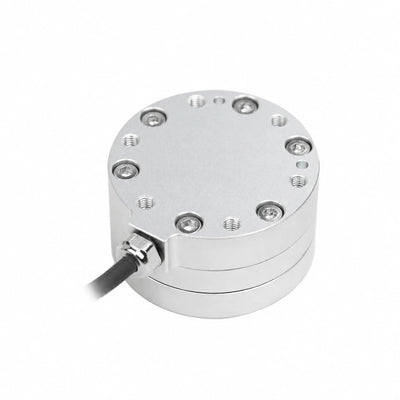
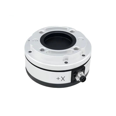
The Kunwei KWR75Ex series is an explosion-proof six-axis force/torque sensor for measuring forces and moments at robotic-arm interfaces. Its 75 mm diameter housing combines circular mounting faces, a central opening and side-mounted electrical connectors. Six versions provide different force and torque ranges, with body heights of 31.5 or 33.5 mm. Shared specifications include 500 Hz sampling, 0.03% FS resolution and an anodized aluminum-alloy housing.
Features
- Measures force along Fx, Fy and Fz and moments about Mx, My and Mz.
- Six range options: KWR75AEx, KWR75BEx, KWR75CEx, KWR75DEx, KWR75EEx and KWR75FEx.
- Circular mounting faces with mounting holes and a central opening; the mounting design supports compatibility with most cobot flanges.
- Side-mounted circular electrical connectors and positive-axis orientation markings.
- Anodized aluminum-alloy construction with IP64 protection and a working temperature range of −10 to 80 °C.
- 300% FS overload level, 0.1% FS repeatability and 0.5% FS accuracy* across all six versions.
Specifications
| Parameter | Unit | KWR75AEx | KWR75BEx | KWR75CEx | KWR75DEx | KWR75EEx | KWR75FEx |
|---|---|---|---|---|---|---|---|
| Range Fx, Fy | N | 50 | 200 | 400 | 500 | 30 | 100 |
| Range Fz | N | 50 | 200 | 500 | 700 | 30 | 100 |
| Range Mx, My | N·m | 2 | 8 | 12 | 18 | 1.5 | 4 |
| Range Mz | N·m | 2 | 8 | 12 | 18 | 1.5 | 4 |
| Diameter | mm | 75 | 75 | 75 | 75 | 75 | 75 |
| Height | mm | 31.5 | 31.5 | 33.5 | 33.5 | 31.5 | 31.5 |
| Material | — | Aluminum alloy | Aluminum alloy | Aluminum alloy | Aluminum alloy | Aluminum alloy | Aluminum alloy |
| Surface treatment | — | Anodized | Anodized | Anodized | Anodized | Anodized | Anodized |
| Overload level | % FS | 300 | 300 | 300 | 300 | 300 | 300 |
| Resolution | % FS | 0.03 | 0.03 | 0.03 | 0.03 | 0.03 | 0.03 |
| Repeatability | % FS | 0.1 | 0.1 | 0.1 | 0.1 | 0.1 | 0.1 |
| Accuracy* | % FS | 0.5 | 0.5 | 0.5 | 0.5 | 0.5 | 0.5 |
| Weight | kg | 0.08 | 0.28 | 0.32 | 0.36 | 0.26 | 0.28 |
| Protection level | — | IP64 | IP64 | IP64 | IP64 | IP64 | IP64 |
| Working temperature | °C | −10 to 80 | −10 to 80 | −10 to 80 | −10 to 80 | −10 to 80 | −10 to 80 |
| Sampling frequency | Hz | 500 | 500 | 500 | 500 | 500 | 500 |
| Supply voltage* | V DC | 12–17 | 12–17 | 12–17 | 12–17 | 12–17 | 12–17 |
| Communication interface | — | RS422 / RS485 / MODBUS / CAN / CANFD / TCP / UDP / EtherCAT / USB, etc. | |||||
Mechanical Dimensions and Mounting
KWR75AEx, KWR75BEx, KWR75EEx and KWR75FEx have a 31.5 mm body height. KWR75CEx and KWR75DEx have a 33.5 mm body height. Positive X, Y and Z directions define the measurement orientation.
| Location | Mounting dimensions and callouts |
|---|---|
| Outside diameter | Ø75; diameter specified as 75 mm. |
| Top-face diameter callouts | Ø50 and Ø63. |
| Top-face pin holes | Two Ø6 holes, diameter tolerance +0.02/0. |
| Top-face threaded holes | Four M6 threaded holes; depth callout 6. |
| Top-face angular layout | 45° offsets on both sides of the Y+ axis. |
| Top-face linear offsets | 25 above and 25 below the horizontal centreline. |
| Top-face geometric tolerance | Position 0.02 relative to datum A. |
| Section A–A screw interface | M4; hexagon socket head cap screws; linear dimension callout 5. |
| Opposite-face pin holes | Two Ø5 holes, diameter tolerance +0.02/0; positional tolerance 0.02 relative to datum A. |
| Opposite-face diameter callout | Ø66 ±0.05. |
| Opposite-face angular layout | Repeated 20° offsets and two 120° ±0.03° callouts. |
| Central opening | Ø31.5, diameter tolerance +0.03/0. |
| Side-view vertical callouts | 24.5, lower dimensions 6 and 9, and overall callouts 31.5 and (33.5). |
Applications
- Robotic-arm contact-load measurement: Measure three force components and three moment components at a tool interface to characterize loads during contact tasks. The circular mounting faces and cobot-oriented mounting design support mechanical integration.
- Force and torque measurement fixtures: Record multi-axis loads at a 500 Hz sampling frequency. Select the version by its individual force and moment ranges, rather than applying one version’s maximum range to the entire series.
Documents and Downloads
- KUNWEI KWR75Ex Drawing Series — Drawing (PDF)
- KUNWEI KWR116 Drawing — 116 Drawing (PDF)
- Kunwei KWR63 Series RS485 — User Manual (PDF)
- KUNWEI 6 Axis Force Sensors Selection — Manual (PDF)
- KUNWEI KWR75 RS422 — User Manual (PDF)
FAQ
How do the six KWR75Ex versions differ?
They differ in force range, moment range, body height and weight. KWR75EEx has 30 N ranges on all three force axes and 1.5 N·m ranges on all three moment axes. KWR75DEx has 500 N Fx/Fy, 700 N Fz and 18 N·m moment ranges. The specification table gives the separate values for every version.
Which versions have the lower body height?
KWR75AEx, KWR75BEx, KWR75EEx and KWR75FEx are 31.5 mm high. KWR75CEx and KWR75DEx are 33.5 mm high; all six versions have a 75 mm diameter.
What measurement axes does the sensor provide?
The sensor measures Fx, Fy and Fz forces and Mx, My and Mz moments, providing six-axis force/torque measurement.
Visual Details
Product Views

Dimensions and Construction

Application Examples