ZhongKeMiDian Spoke Load Cell, 20 kg–300 t Tension & Compression
ZhongKeMiDian Spoke Load Cell, 20 kg–300 t Tension & Compression
ZhongKeMiDian
পিকআপের উপলভ্যতা লোড করা যায়নি


Overview
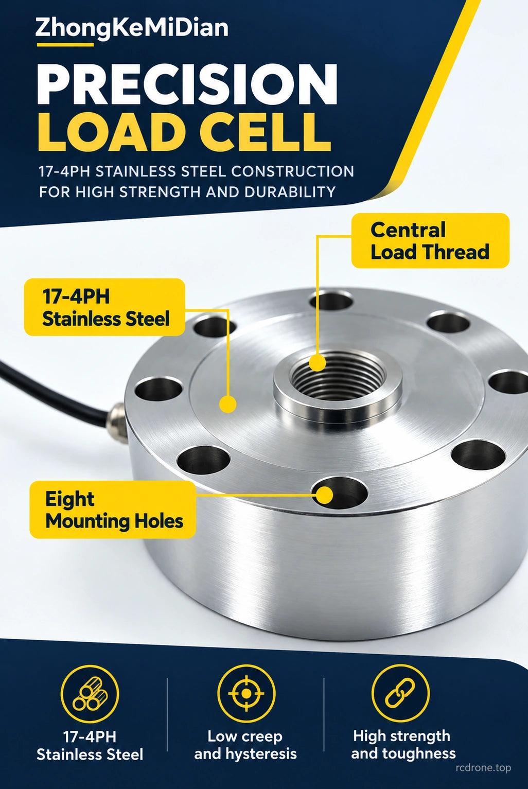
The ZhongKeMiDian spoke load cell measures tension and compression through a central threaded load point and an eight-hole mounting pattern. Fourteen capacity options span 20 kg to 300 metric tonnes, with body diameter and thread size increasing by capacity group. Its strain-gauge bridge output suits weighing, force testing and load-monitoring systems when paired with suitable signal conditioning. Choose the capacity and mounting dimensions for your installation.
Features
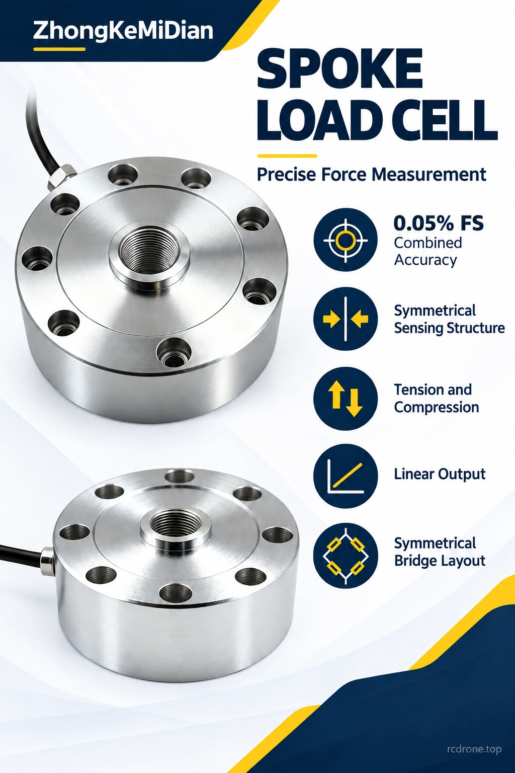
- Bidirectional measurement: measure tensile and compressive loads with a symmetrical sensing structure and bridge layout.
- Capacity-specific sizes: select from 14 rated capacities, with body diameters from 72 to 350 mm.
- Central load introduction: a threaded central boss and eight mounting holes provide a defined load path for fixtures and weighing assemblies.
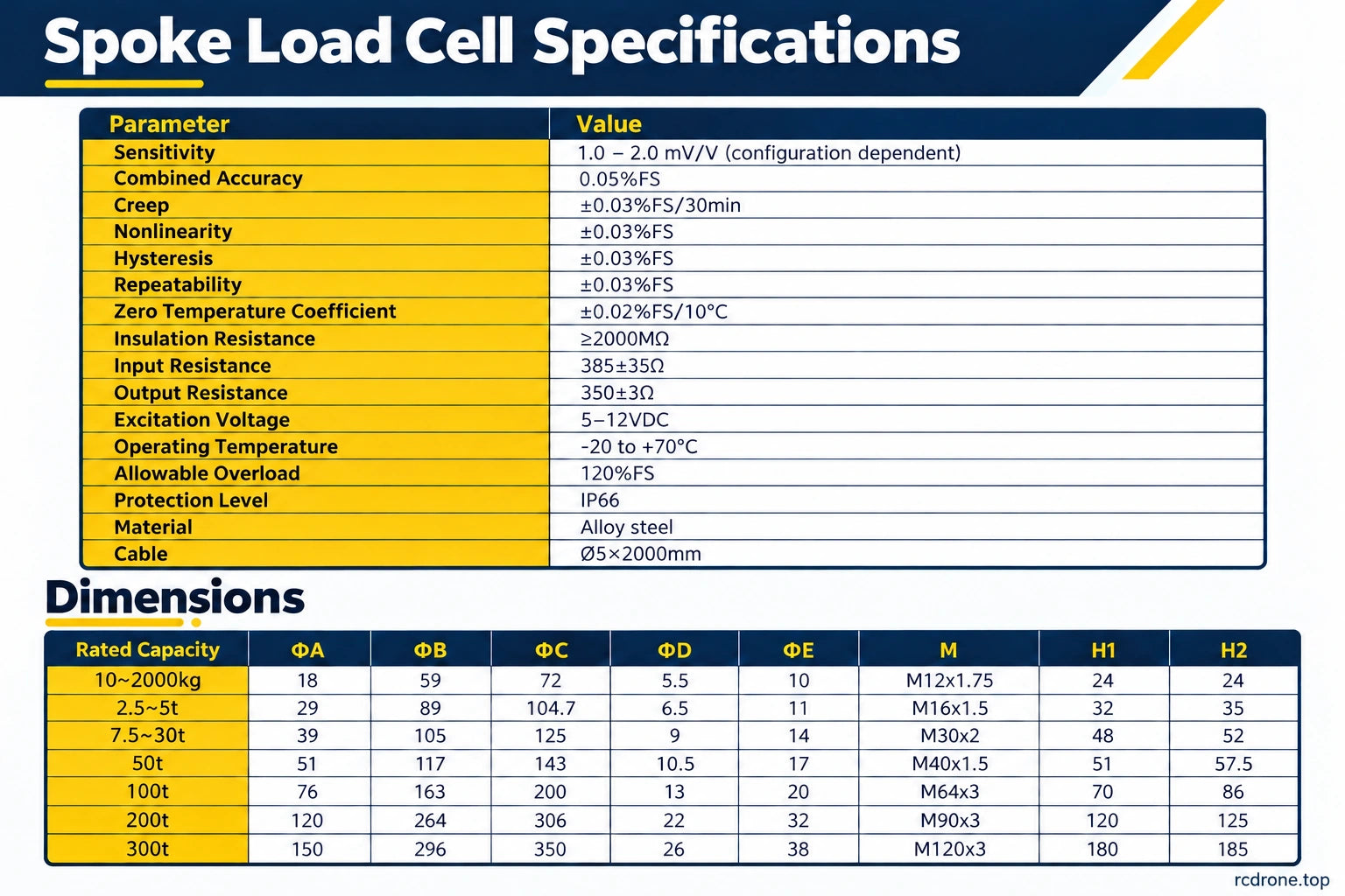
- Measurement performance: combined accuracy of 0.05% FS, with nonlinearity, hysteresis and repeatability specified separately below.
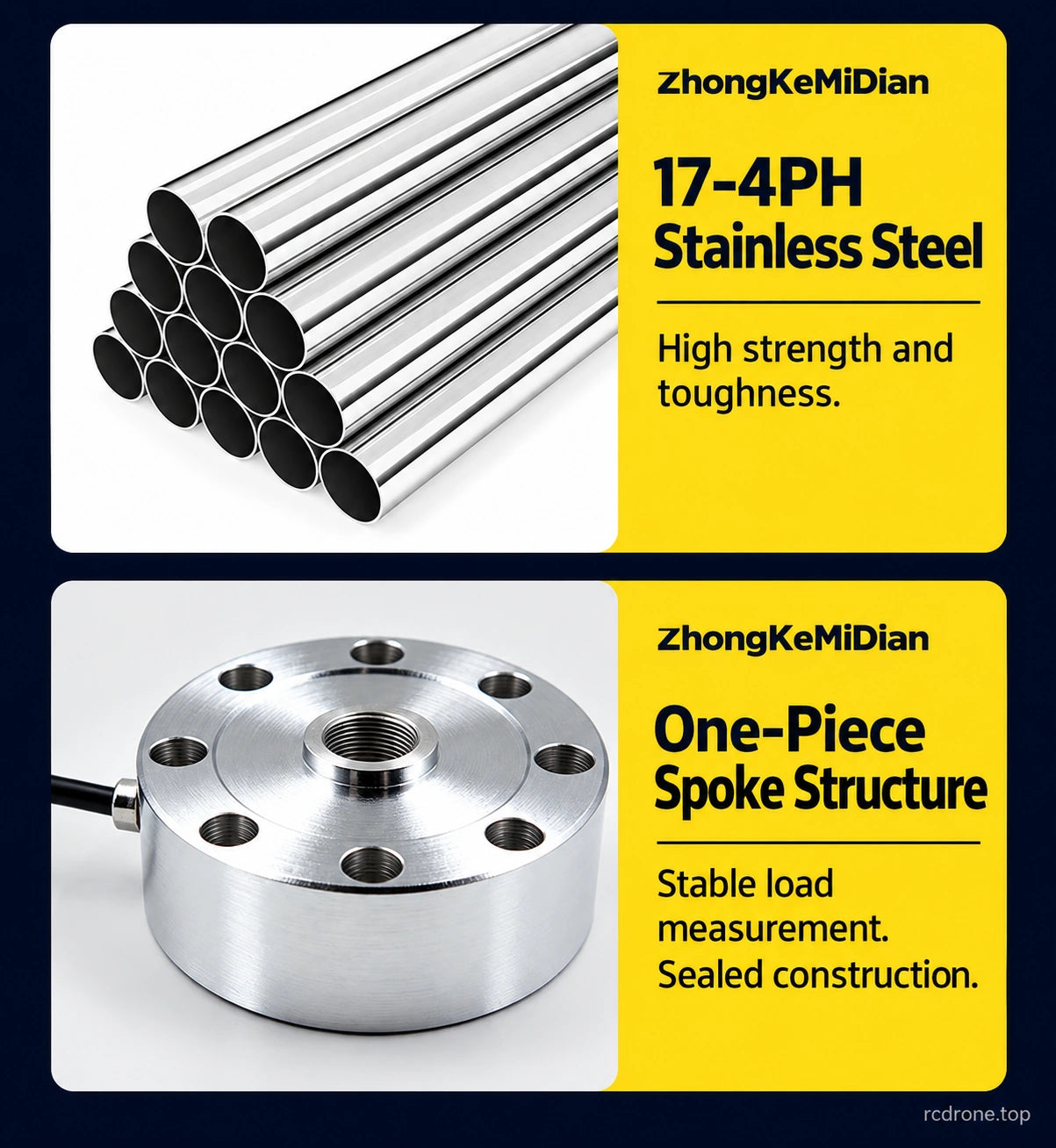
- Metal construction: 17-4PH stainless-steel construction and a one-piece spoke structure support stable load measurement.
- Sealed design: IP66 protection and a 2 m cable for integration into measurement equipment.
Specifications
| Sensor type | Spoke-style strain-gauge load cell |
|---|---|
| Loading direction | Tension and compression |
| Available rated capacities | 20, 50, 100, 500 kg; 1, 2, 5, 10, 20, 30, 50, 100, 200, 300 t |
| Nominal sensitivity | 1.0–2.0 mV/V, configuration dependent; use the calibration sensitivity for the selected unit. |
| Combined accuracy | 0.05% FS |
| Nonlinearity | ±0.03% FS |
| Hysteresis error | ±0.03% FS |
| Repeatability error | ±0.03% FS |
| Creep | ±0.03% FS / 30 min |
| Zero temperature coefficient | ±0.02% FS / 10 °C |
| Input resistance | 385 ±35 Ω |
| Output resistance | 350 ±3 Ω |
| Insulation resistance | ≥2000 MΩ |
| Excitation voltage | 5–12 VDC |
| Operating temperature | −20 to +70 °C |
| Allowable overload | 120% FS |
| Ingress protection | IP66 |
| Construction material | 17-4PH stainless steel |
| Cable | Ø5 mm × 2000 mm long |
FS means full scale. Capacity labels in kg and t describe rated load capacity, not the sensor's own weight; 1 t equals 1000 kg. Allowable overload is not a continuous measurement range. This is a single-axis tension/compression load cell.
Capacity and Mounting Dimensions
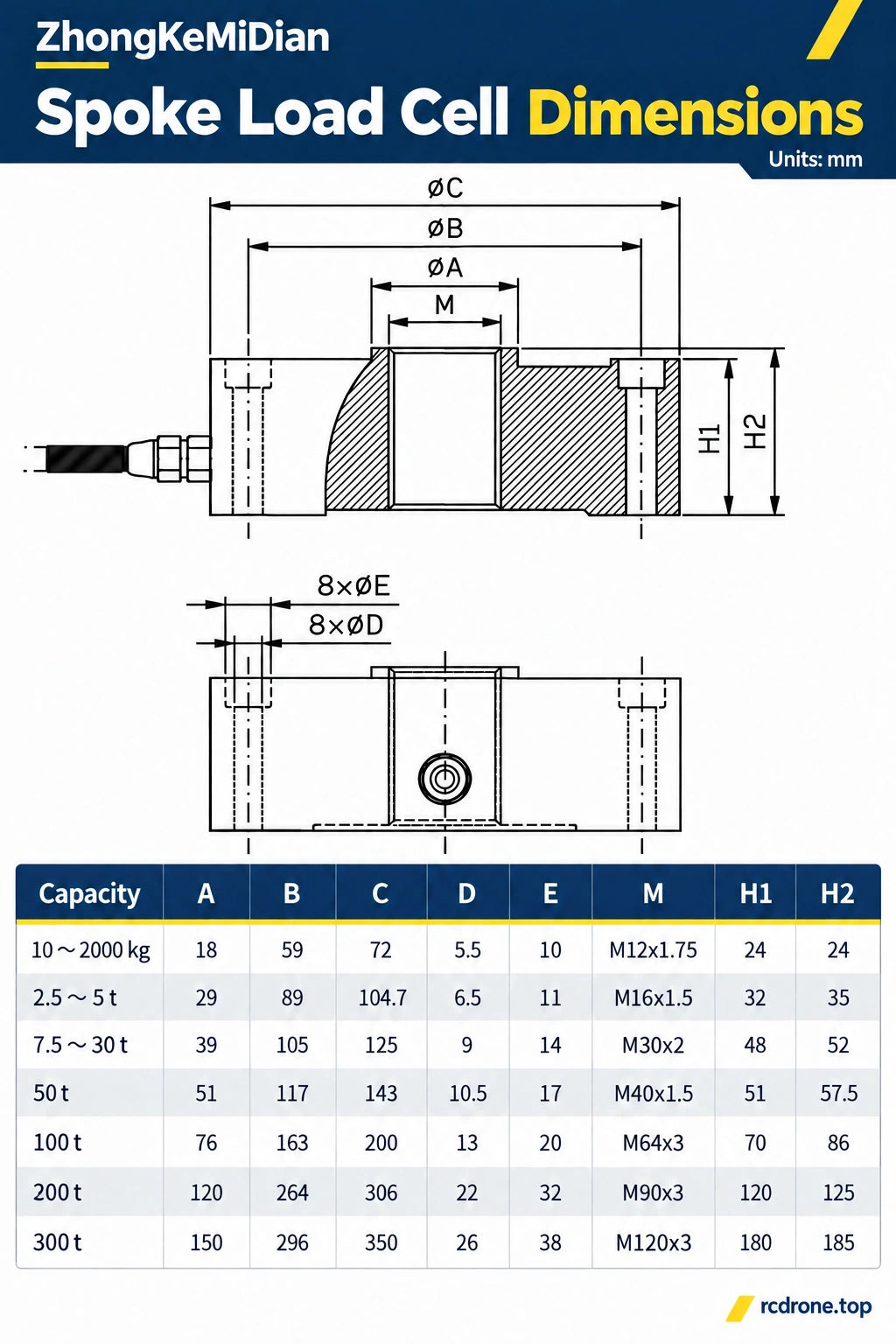
Choose the rated load first, then check body diameter, central thread and mounting-hole dimensions. All dimensions below are in millimetres; refer to the dimensioned drawing in Visual Details for A, B, C, D, E, H1 and H2. C is the outside diameter, M the central thread, and the drawing identifies eight ØD holes with eight ØE counterbores.
| Selected capacity | A | B | C | D | E | M | H1 | H2 |
|---|---|---|---|---|---|---|---|---|
| 20 / 50 / 100 / 500 kg; 1 / 2 t | 18 | 59 | 72 | 5.5 | 10 | M12×1.75 | 24 | 24 |
| 5 t | 29 | 89 | 104.7 | 6.5 | 11 | M16×1.5 | 32 | 35 |
| 10 / 20 / 30 t | 39 | 105 | 125 | 9 | 14 | M30×2 | 48 | 52 |
| 50 t | 51 | 117 | 143 | 10.5 | 17 | M40×1.5 | 51 | 57.5 |
| 100 t | 76 | 163 | 200 | 13 | 20 | M64×3 | 70 | 86 |
| 200 t | 120 | 264 | 306 | 22 | 32 | M90×3 | 120 | 125 |
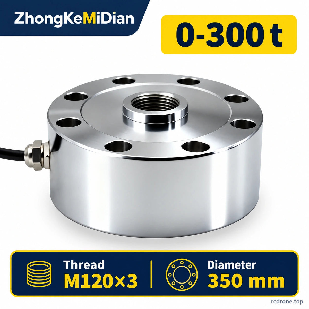
| 300 t | 150 | 296 | 350 | 26 | 38 | M120×3 | 180 | 185 |
Applications
- Industrial weighing: integrate the load cell into a weighing fixture or platform with the capacity and support arrangement matched to the load.
- Tension and compression testing: measure axial loads in test rigs using the central thread and a suitably aligned fixture.
- Press and assembly monitoring: track applied force during pressing or assembly with suitable amplification and data acquisition.
- Load-monitoring systems: connect the bridge signal to compatible instrumentation for display, recording or controller feedback.
Installation and Signal Conditioning
- Match the capacity, central thread and mounting dimensions to the fixture. Apply the load along the intended sensing axis and limit unwanted side loads and bending moments.
- Use the eight-hole mounting pattern and appropriate fasteners for the selected size; do not interchange hardware across capacity groups without checking dimensions.
- Connect the bridge to compatible instrumentation using the correct wiring information. Verify pinout, excitation and polarity before powering the system.
- Zero and calibrate the complete installation for its intended load direction and measurement range. Keep operation within the rated load, temperature and excitation limits.
- Route the cable clear of sharp edges and moving parts, with strain relief at the connection.
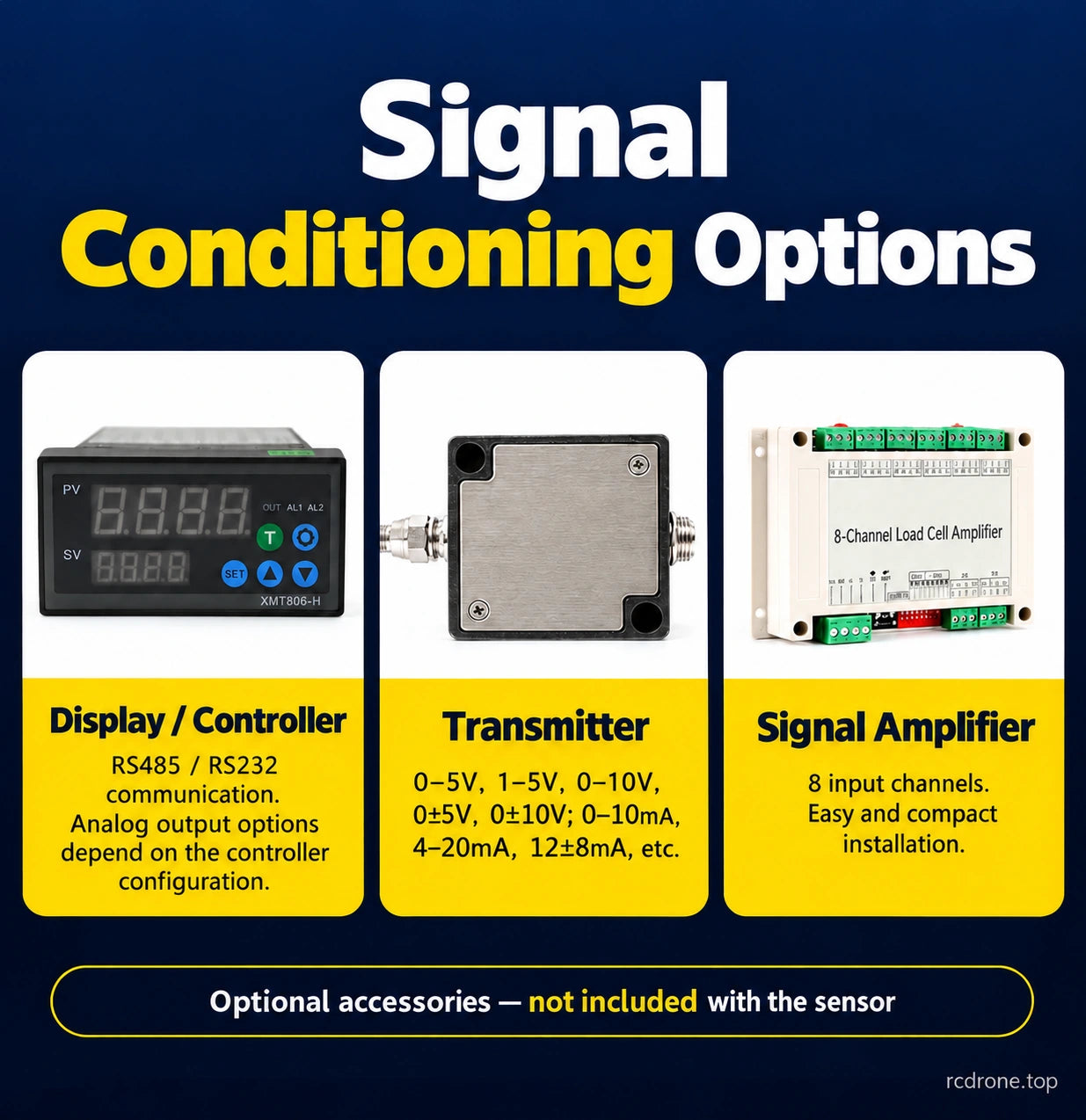
The sensor provides a low-level mV/V bridge signal. A display/controller, transmitter or amplifier may be added separately. Accessory examples include displays with RS485/RS232 communication, transmitters offering 0–5 V, 1–5 V, 0–10 V, ±5 V or ±10 V outputs and 0–10 mA, 4–20 mA or 12 ±8 mA outputs, plus eight-input signal-conditioning modules. These describe optional accessory configurations, not outputs or ports built into every sensor. Select the signal conditioner for the sensor's bridge sensitivity and excitation requirements.
What's Included
- 1 × ZhongKeMiDian spoke load cell in the selected capacity, with its attached cable.
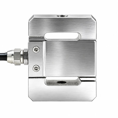
Displays, transmitters, amplifiers, adapters, mounting fixtures and fasteners are not included. The product images illustrate the spoke-style construction; use the selected capacity's dimension row for installation sizing.
Visual Details