CHIHAI CHF-GW12T-050S Mini Worm Gear Motor, 6V/12V Single or Dual Shaft
CHIHAI CHF-GW12T-050S Mini Worm Gear Motor, 6V/12V Single or Dual Shaft
CHIHAI MOTOR
No se pudo cargar la disponibilidad de recogida


Overview
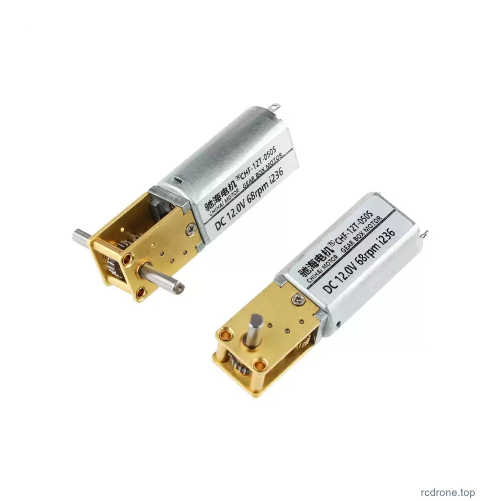
The CHIHAI MOTOR CHF-GW 12T-050S DC gear motor combines a miniature brushed motor with a metal worm-and-spur gearbox and 90-degree output. Select the actual 6 V or 12 V winding, reduction ratio, single- or dual-ended D shaft, and the motor-only or accessory package for your mechanism.
Features
- Metal reduction gears and copper-wire armature winding.
- Compact right-angle transmission for constrained mounting layouts.
- Worm-drive resistance to back-driving when power is removed.
- Single 8 mm or dual 10 mm-per-side shaft references.
- Reversible DC operation with optional PWM or enclosed reversing controls.
- Optional green bracket and controller/power-supply packages.
Specifications
| Brand / model | CHIHAI MOTOR / CHF-GW 12T-050S |
| Drive | Permanent-magnet brushed DC motor with metal worm-and-spur reduction transmission; right-angle output |
| Selectable winding | 6 V or 12 V DC according to configuration |
| Reduction choices | 42: 1, 236: 1, 302: 1, 603: 1 and 1030: 1 in the available combinations; 118: 1 is a family reference only |
| Output shaft | 3 mm diameter D shaft, diameter tolerance+0/-0.03 mm; 2.5 mm nominal across-flat reference, with configuration-specific tolerances |
| Single shaft | 8.0±0.3 mm projection; 7.5 mm flat length,+0.03/0 mm; 2.5 mm across flat,+0/-0.05 mm |
| Dual shaft | 10.0±0.3 mm projection on each side; 9.2 mm flat length,+0.03/0 mm; 2.5 mm across flat,+0/-0.06 mm; 0.5 mm shoulders |
| Body length | 44.3±0.3 mm drawing reference; motor section 26.9 mm REF |
| Gearbox face | 18.0×12.0 mm plan references; 10.0 mm gearbox-height reference |
| Motor cross-section | 15.5 mm round-envelope and 11.8 mm flat-body references; rear feature 4.7 mm |
| Mount / front features | Two 1.4 mm-diameter mounting-hole references; 8.50 mm spacing; 4.0 mm output-center/end reference; 1.8 mm edge reference |
| Shaft support feature | 4.0 mm diameter collar reference |
| Mass | Approximately 24 g motor reference; depends on reduction and configuration |
| Load limit | Recommended gearbox-load torque no more than 3kgf.cm; avoid stall and running reversals |
| Self-locking behavior | Worm drive resists back-driving when unpowered; verify retention under actual load. No certified holding-brake rating or safety lifting capacity is specified. |
12 V Performance Reference
| Ratio : 1 | No-load rpm | Rated rpm | Rated kgf.cm | Rated N.m | Stall torque kgf.cm /limit |
|---|---|---|---|---|---|
| 42 | 380 | 300 | 0.1 | 0.01 | ≤0.35 |
| 118 | 135 | 105 | 0.3 | 0.03 | ≤1.0 |
| 236 | 68 | 53 | 0.65 | 0.064 | ≥2.5 |
| 302 | 53 | 41 | 0.8 | 0.079 | Load ceiling |
| 603 | 27 | 20 | 1.6 | 0.16 | Load ceiling |
| 1030 | 16 | 12 | 2.4 | 0.24 | Load ceiling |
6 V Performance Reference
| Ratio : 1 | No-load rpm | Rated rpm | Rated kgf.cm | Rated N.m | Stall torque kgf.cm /limit |
|---|---|---|---|---|---|
| 42 | 190 | 140 | 0.05 | 0.005 | ≤0.17 |
| 118 | 67 | 50 | 0.15 | 0.015 | ≤0.5 |
| 236 | 33 | 25 | 0.32 | 0.031 | ≤1.2 |
| 302 | 26 | 20 | 0.4 | 0.039 | ≤1.50 |
| 603 | 13 | 10 | 0.8 | 0.079 | Load ceiling |
| 1030 | 8 | 6 | 1.2 | 0.12 | Load ceiling |
118: 1 is not an available retail choice. No-load and rated speeds are separate operating conditions. Stall-torque inequality signs are retained as distinct reference limits; they do not establish a uniform guaranteed stall or holding torque. Avoid stall, and keep gearbox load within the recommended 3kgf.cm ceiling. This limit is not a continuous-duty lifting or holding-brake rating.
Voltage-Specific Electrical Reference
| Winding | Power reference | No-load current | Rated current | Stall current |
|---|---|---|---|---|
| 12 V | 0.55 W | ≤85 mA | ≤0.23 A | ≤1.0 A |
| 6 V | 0.15 W | ≤65 mA | ≤0.18 A | ≤0.6 A |
The performance reference uses the type 11 input motor; 11 identifies the input-motor type, not an 11 V supply. The 0.55 W and 0.15 W figures are separate power references, not a substitute for the rated torque/speed points. Match the selected 6 V or 12 V winding rather than applying the general 3–12 V family operating range to every configuration.
Shaft and Mounting Fit
Both shaft arrangements use a 3 mm D shaft with a 2.5 mm across-flat reference. The single-ended drawing has 8.0±0.3 mm projection; the dual-ended drawing has 10.0±0.3 mm on each side. These are different mechanical configurations. Check the full drawing, hole positions, shaft clearance and mounting arrangement before making a bracket or coupler. The body drawing also marks a 1.9±0.2 mm rear-projection reference. A photograph showing both shaft arrangements is a comparison, not a two-motor package.
Connection and Control
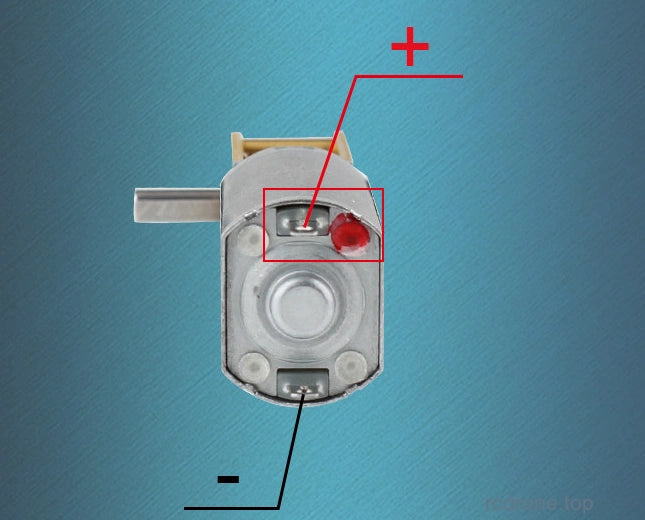
The bare motor has two DC terminals. The red-marked terminal is the positive reference; reverse motor polarity after stopping to reverse rotation. Do not reverse the DC input polarity of an electronic controller. Stop the motor before changing direction to protect the gearbox.
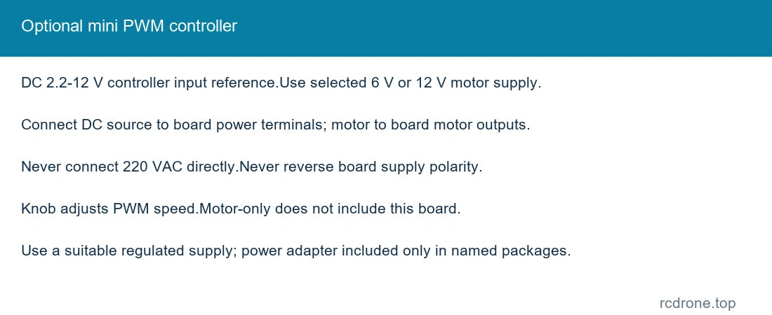
The mini PWM board has a 2.2–12 V DC input reference. Connect its DC supply to the power terminals and its motor-output terminals to the motor. Never connect 220 V AC directly to the board or motor; wrong polarity can damage the board. Use a supply suitable for the selected motor winding.
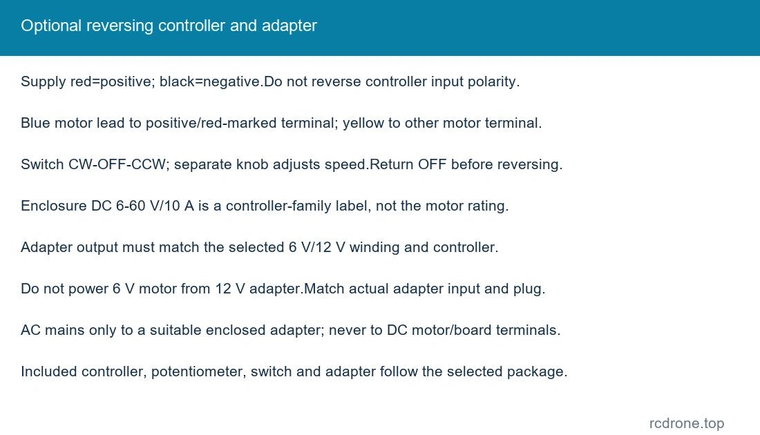
The enclosed reversing-controller diagram uses red for DC supply positive and black for supply negative. Its blue motor lead connects to the positive/red-marked motor terminal and yellow to the other terminal; swapping motor leads reverses the direction reference. The three-position switch selects CW–OFF–CCW and the separate knob adjusts speed. Keep the adapter and controller input polarity correct, and return to OFF before changing direction. The pictured enclosure is marked DC 6–60 V/10 A as a controller-family label; these values are not the motor operating voltage or a verified motor-current rating.
A power adapter is included only where named. Its DC output must match the selected 6 V or 12 V motor and suitable controller. Do not connect a 6 V motor to a 12 V adapter. Match the actual adapter input rating and plug to your location; AC mains is connected only to a suitable enclosed adapter, never to the DC motor/controller terminals.
Selection and Speed Adjustment
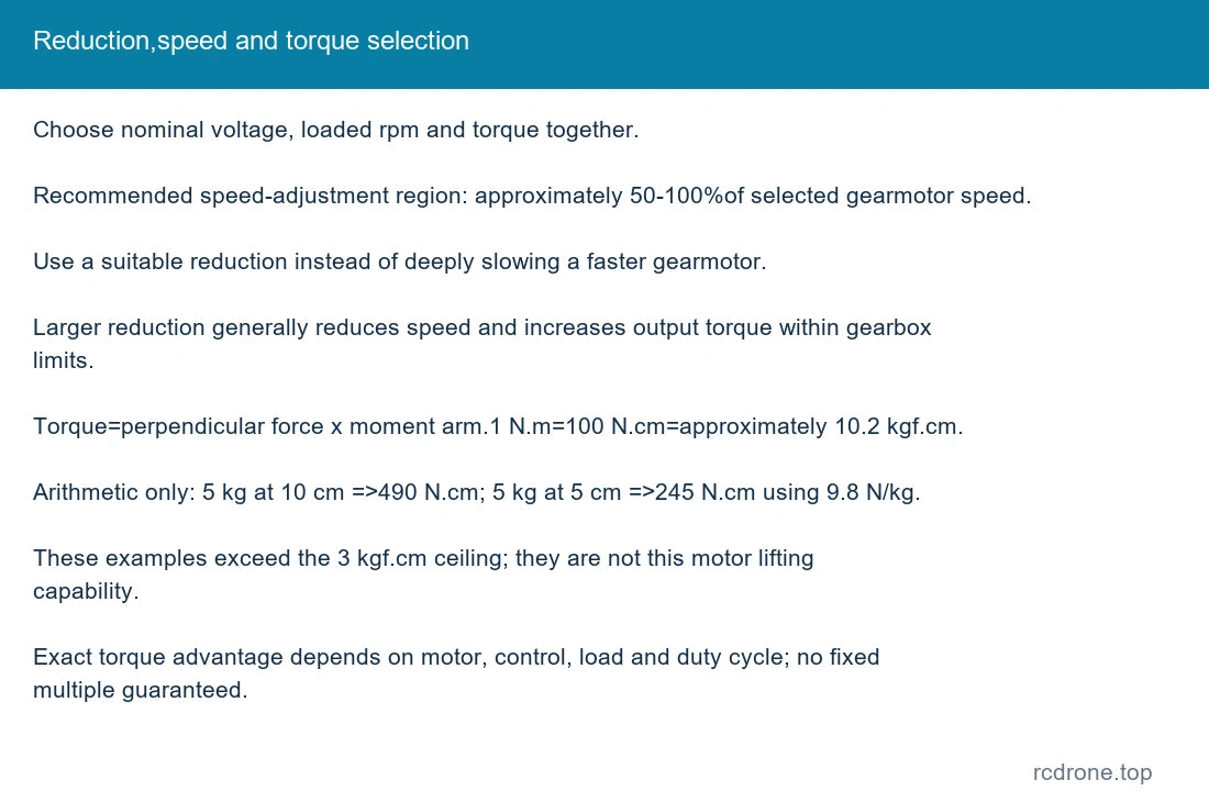
Select using voltage, required loaded speed and torque together. The recommended speed-adjustment region is approximately 50–100% of the selected gearmotor speed; select an appropriate reduction instead of relying on deep speed reduction from a faster motor. More reduction generally reduces output speed and increases available gearbox torque within its limits. The exact torque margin depends on the motor, controller, load and duty cycle.
Torque equals perpendicular force multiplied by moment arm. As an arithmetic illustration, a 5kg force at 10cm requires 490N.cm; at 5cm it requires 245N.cm, using 9.8N/kg. Unit conversion: 1N.m=100N.cm≈10.2kgf.cm. These illustrations exceed this motor's recommended 3kgf.cm gearbox-load ceiling and do not state its lifting capacity. The same load at a longer arm requires proportionally more torque.
Applications
Miniature robots, small vehicle and model mechanisms, motorized toys, smart-home mechanisms, camera pan mechanisms and other compact drives that fit the selected voltage, speed, torque and right-angle shaft arrangement.
What's Included
| Selected package | Contents |
|---|---|
| Motor Only | One selected single- or dual-shaft motor. |
| Motor + Green Bracket | One selected motor and one pictured green mounting bracket. |
| Motor + Mini PWM Controller | One selected motor and one mini PWM control board. |
| Motor + Mini PWM Controller + Power Supply | One selected motor, one mini PWM control board and one DC power adapter. |
| Motor + Reversing Controller | One selected motor and one enclosed reversing controller with speed knob and CW-OFF-CCW switch. |
| Motor + Reversing Controller + Power Supply | One selected motor, one reversing controller with knob/switch, and one DC power adapter. |
Each configuration supplies one selected motor. Accessories are included only when named. A complete robot, toy, car, chassis, coupler or additional motor is not included. Motor-only and controller-without-supply packages require a suitable external power source.
FAQ
Does dual shaft mean two motors?
No. It is one motor with output shafts on both sides, each with a 10 mm projection reference.
Can I select 118: 1?
No. It remains in the family performance tables for comparison but is unavailable as a retail configuration.
Can the worm gear replace a certified holding brake?
Verify back-driving and retention with the actual load. No certified holding-brake or safety lifting rating is specified.
Does every controller package include a power adapter?
Only packages that explicitly name a power supply include an adapter. Match its output to the selected motor winding.
What does type 11 mean in the performance reference?
It identifies the input-motor type. The selectable nominal supplies are 6 V and 12 V.
Visual Details