


Modul Kamera Linear CCD 128-Piksel TSL1401 3.3-5V Output AO untuk MCU Kereta Pintar Pengesan Garisan
Modul Kamera Linear CCD 128-Piksel TSL1401 3.3-5V Output AO untuk MCU Kereta Pintar Pengesan Garisan
Yahboom
Tidak dapat memuatkan ketersediaan pengambilan
Overview
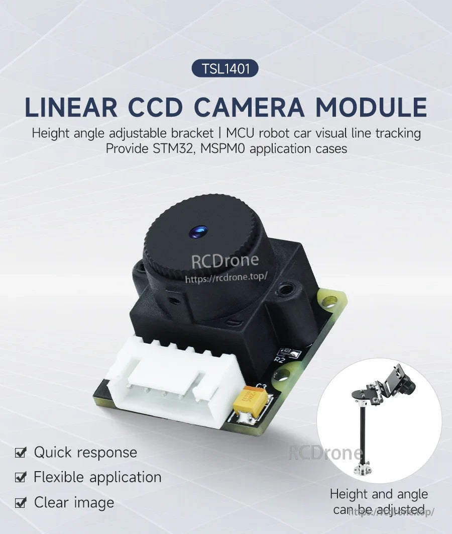
Modul Kamera CCD Linear TSL1401 menggunakan CCD linear 128-piksel (128 × 1) untuk menukar adegan yang diimbas menjadi isyarat elektrik. Data nilai kelabu yang dikumpul dikeluarkan sebagai voltan analog pada pin AO dan boleh diambil sampel oleh penukar A/D mikropengawal untuk penjejakan garis visual kereta robot, pengenalan laluan, penjejakan, pengelakan halangan, dan tugas pemprosesan imej lain. Modul ini direka untuk tindak balas pantas dan kurang terjejas oleh cahaya ambien, menyokong penggunaan penjejakan berkelajuan tinggi di dalam dan luar bangunan.
Ciri Utama
- CCD linear 128-piksel (128 × 1), pengambilan imbas linear
- Voltan kerja: DC 3.3V–5V
- Jarak pengesanan: dalam 5–40 cm (tidak sesuai untuk ujian pandangan jauh kerana lensa)
- Lensa: lensa tanpa distorsi 56 darjah
- Tindak balas cepat; imej jelas; aplikasi fleksibel
- 5Pin XH2 di atas papan.54 penyambung anti-balik; pinout: GND, VCC, AO, CLK, SI
- Bracket boleh laras ketinggian/anjakan tersedia (pilihan)
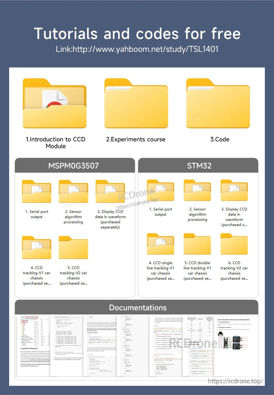
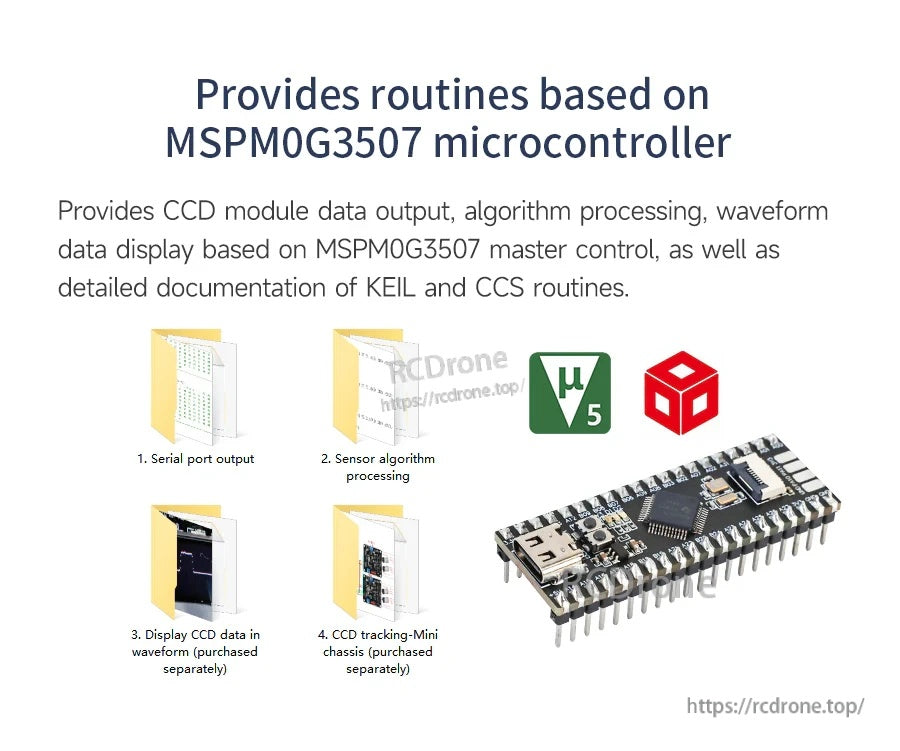
- Kod pemacu STM32 dan tutorial disediakan (juga ditunjukkan dengan kes aplikasi STM32/MSPM0)
Untuk soalan pendawaian atau pemeriksaan keserasian pra-jualan, hubungi [email protected] or lawati https://rcdrone.top/.
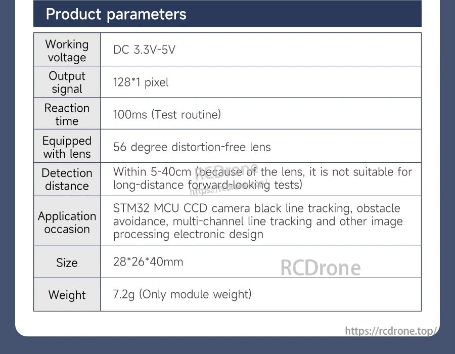
Spesifikasi
| Isyarat output CCD | 128*1 piksel |
| Voltan kerja | DC 3.3V-5V |
| Waktu reaksi | 100ms (Rutin ujian) |
| Lens | Lens tanpa distorsi 56 darjah |
| Jarak pengesanan | Dalam 5-40cm (kerana lensa, ia tidak sesuai untuk ujian pandangan jauh) |
| Kesempatan aplikasi | Pengesanan garis hitam kamera CCD STM32 MCU, penghindaran halangan, pengesanan garis pelbagai saluran dan reka bentuk elektronik pemprosesan imej lain |
| Saiz | 28*26*40mm |
| Berat | 7.2g (Hanya berat modul) |
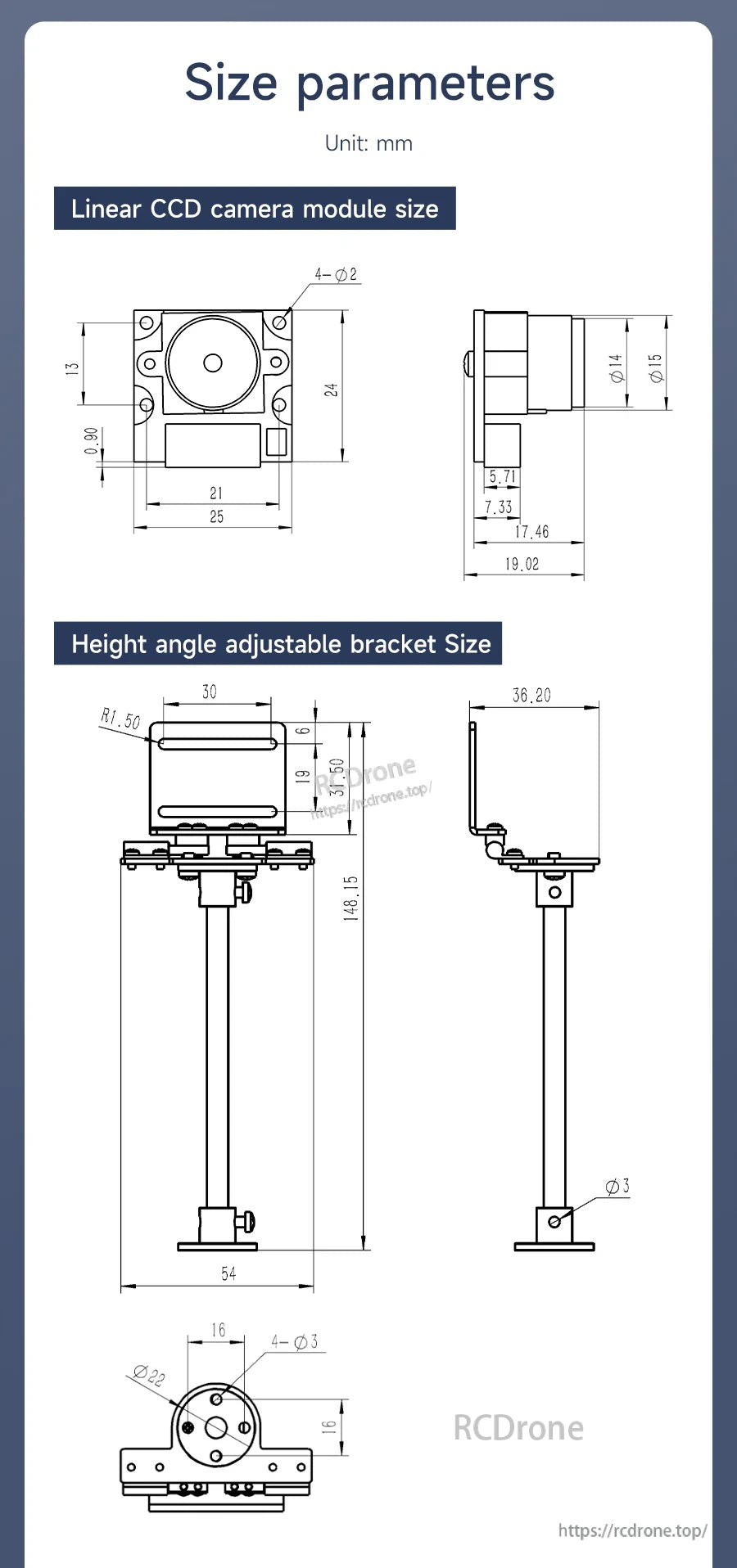
Dimensi lukisan mekanikal (unit: mm)
| Lubang pemasangan modul | 4-φ2 |
| Lebar depan modul | 25 |
| Lebar dalam modul | 21 |
| Ketinggian depan modul | 24 |
| Ketinggian rujukan modul | 13; 9.00 |
| Panjang rujukan sisi modul | 5.71; 7.33; 17.46; 19.02 |
| Diameter lensa/perumahan optik | φ14; φ15 |
Dimensi braket boleh laras ketinggian/anjakan (unit: mm)
| Julat larasan ketinggian (ketinggian modul) | 1.2~9.5cm |
| Lebar plat atas | 30 |
| Radius sudut plat atas | R1.50 |
| Dimensi menegak bracket | 19; 35.50 |
| Ketinggian keseluruhan (lukisan) | 148.15 |
| Lebar profil sisi (lukisan) | 36.20 |
| Lebar asas (lukisan) | 54 |
| Diameter ciri bawah | φ22 |
| Lubang pemasangan bawah | 4-φ3 |
| Lubang tambahan | φ3 |
| Dimensi rujukan ditunjukkan | 16 (diulang pada lukisan asas) |
| Sudut pitch | Boleh disesuaikan dengan fleksibel |
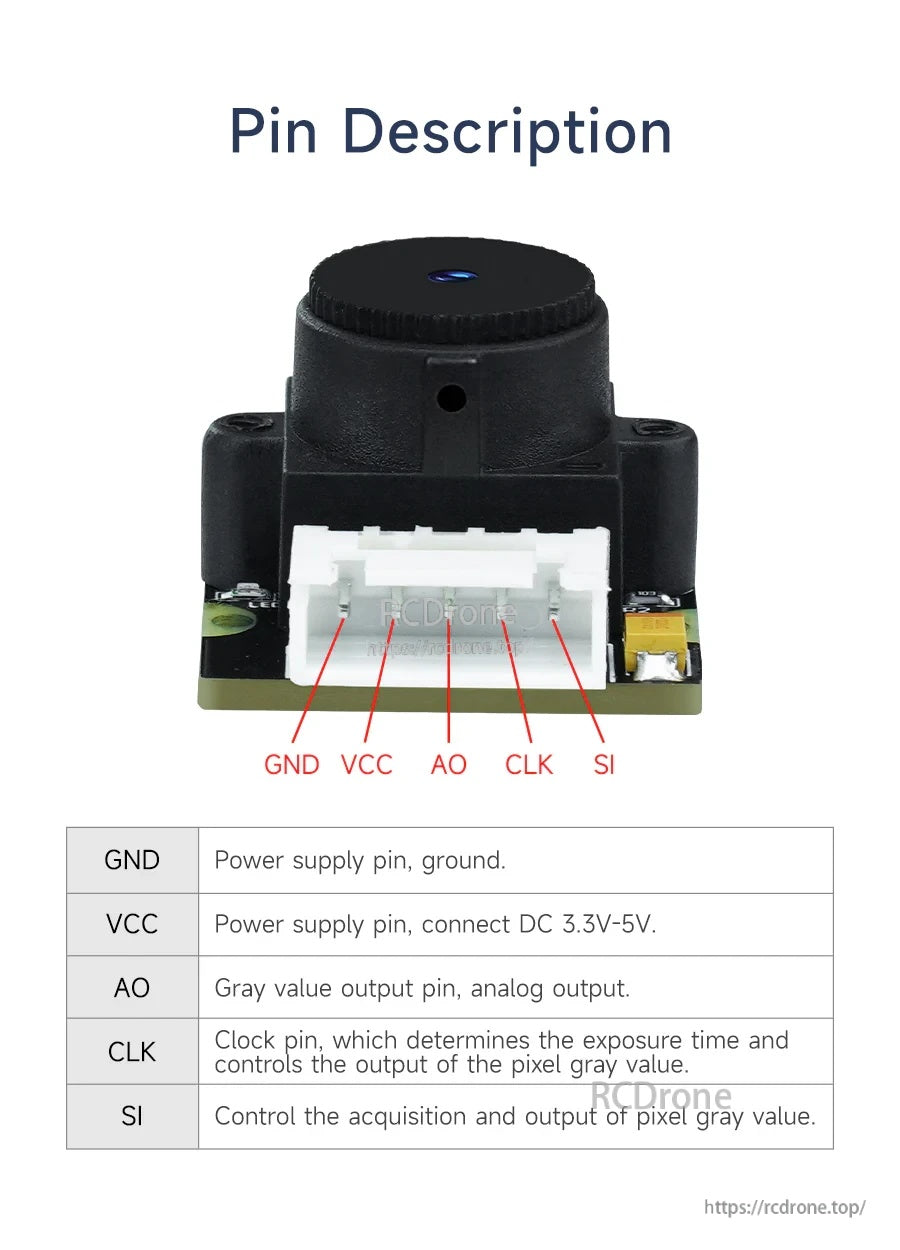
Penyambungan pin
| GND | Pin bekalan kuasa, tanah. |
| VCC | Pin bekalan kuasa, sambungkan DC 3.3V-5V. |
| AO | Pin output nilai kelabu, output analog. |
| CLK | Pin jam, yang menentukan masa pendedahan dan mengawal output nilai kelabu piksel. |
| SI | Mengawal pengambilan dan output nilai kelabu piksel. |
Permohonan
- Pengesanan garis visual kereta robot MCU (pengesanan garis tunggal, berganda, dan pelbagai saluran)
- Pengenalan dan pengesanan laluan kereta pintar
- Pengelakan halangan berdasarkan pemprosesan ciri imej/garis
- Pembangunan aplikasi STM32 dan projek pembelajaran (kes aplikasi juga ditunjukkan untuk MSPM0)
Butiran
Modul TSL1401 menukarkan satu garis 128 piksel menjadi output nilai kelabu analog untuk pengesanan garis yang cepat.
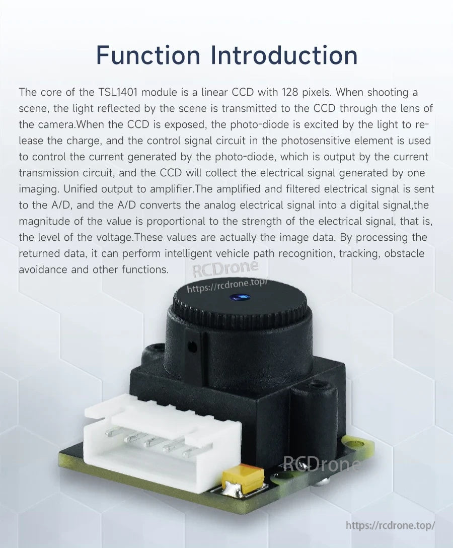
Direka untuk projek MCU, output AO analog boleh diambil sampel oleh ADC untuk pengesanan dan tugas visi yang mudah.
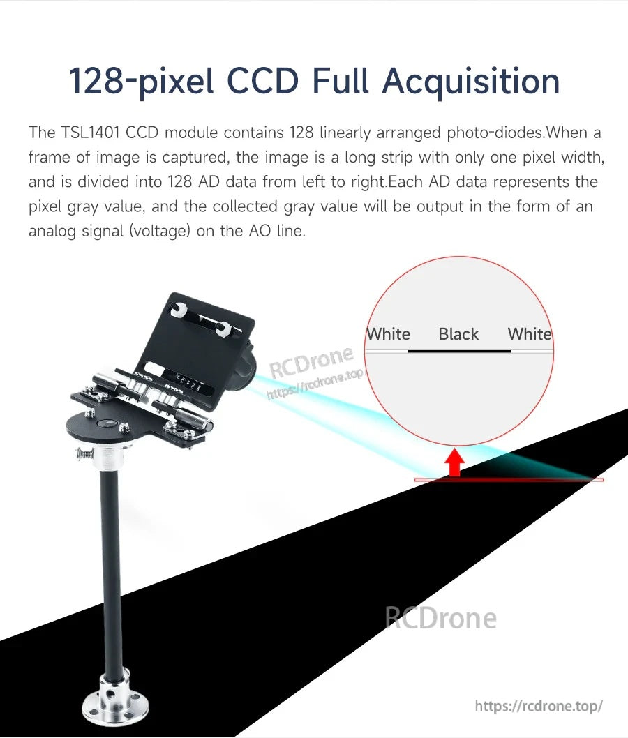
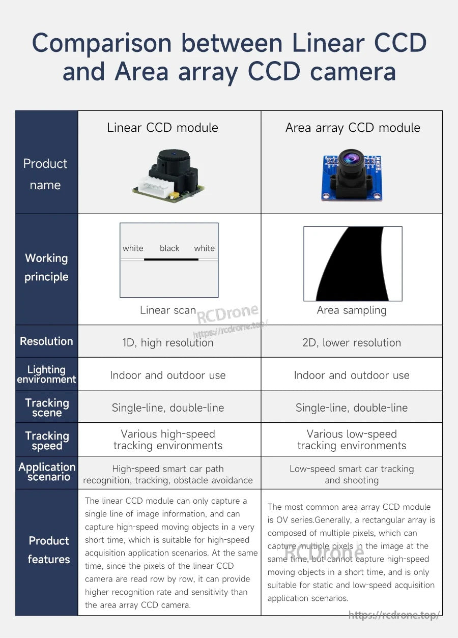
Pemindaian garis 1D mengurangkan beban pemprosesan berbanding dengan kamera bingkai penuh sambil masih menangkap kontras tepi dan garis.
Pemindaian linear membantu mencapai pengesanan kelajuan yang lebih tinggi dengan mengambil sampel hanya data garis yang diperlukan untuk navigasi.
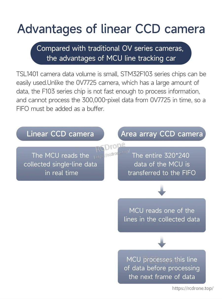
Data yang kurang setiap bingkai bermakna firmware yang lebih sederhana dan respons yang lebih cepat pada pengawal mikro biasa.
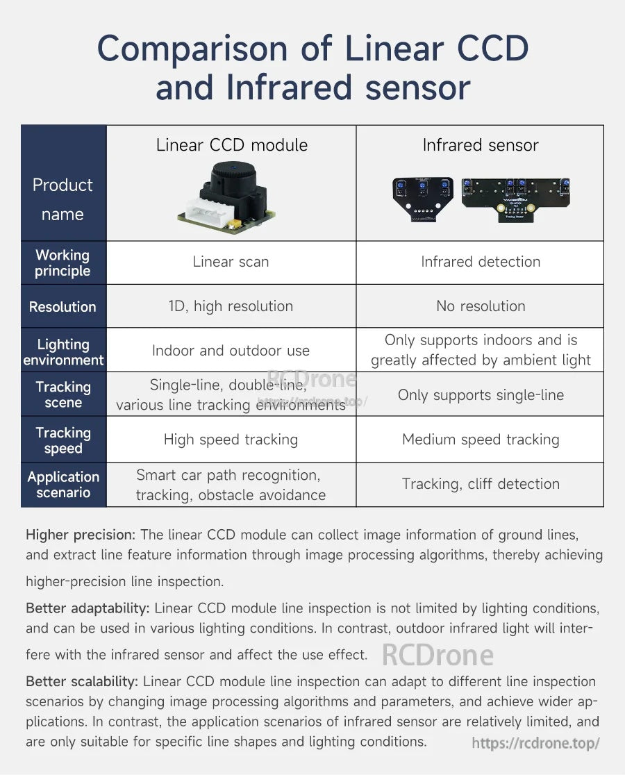
Untuk aplikasi di mana cahaya ambien berbeza, pendekatan CCD linear dapat memberikan maklumat garis yang lebih konsisten berbanding dengan pengesanan IR.
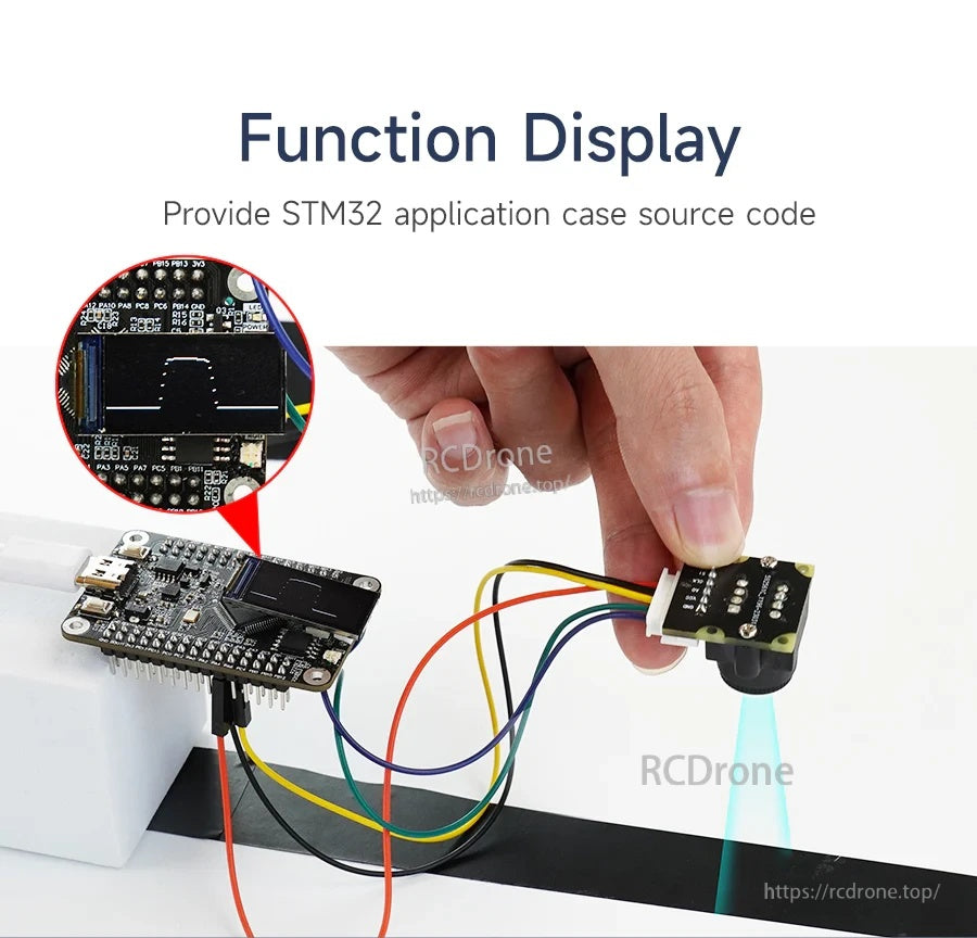
Contoh pendawaian dengan papan STM32 untuk memperoleh output AO dan memacu isyarat masa SI/CLK.
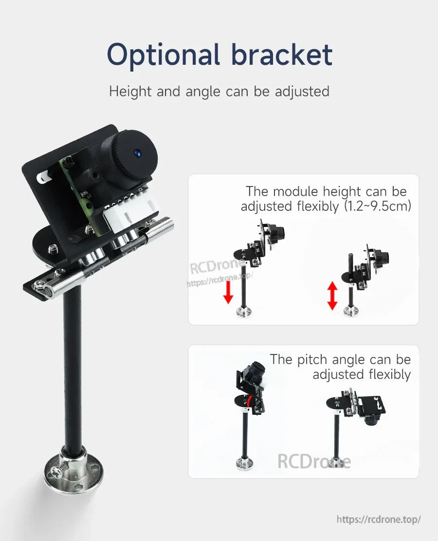
Bracket pilihan membolehkan ketinggian pemasangan dan sudut cerun yang fleksibel semasa menyelaraskan jarak pengesanan dan bidang pandangan.
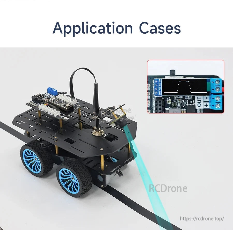
Kes penggunaan biasa: pengesanan garis visual kereta robot untuk pengenalan laluan dan logik pengelakan halangan.
Pelan mekanikal menyediakan lokasi lubang pemasangan dan dimensi keseluruhan untuk reka bentuk penutup dan chasis.
Pinout: GND dan VCC memberi kuasa kepada modul, AO mengeluarkan nilai kelabu analog, dan SI/CLK mengawal masa pengambilan.
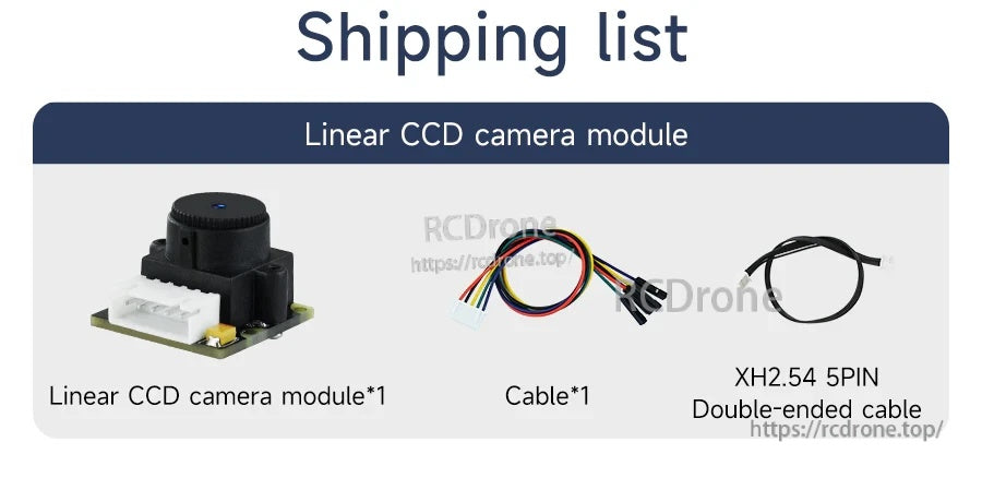
Pakej termasuk modul dan kabel 5-pin untuk sambungan cepat ke pengawal atau persediaan ujian.
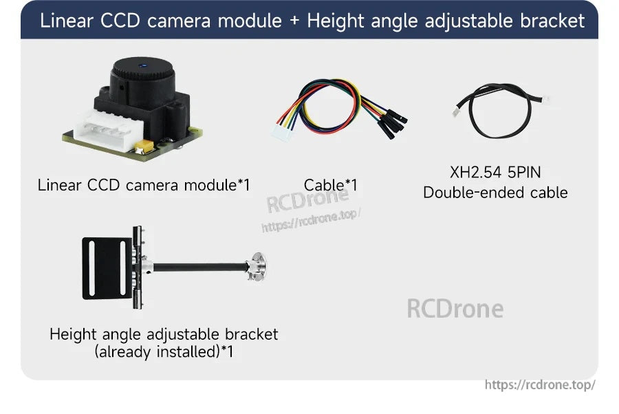
Modul kamera CCD linear TSL1401 dilengkapi dengan bracket yang boleh disesuaikan tinggi/anjakan serta kabel harness dan kabel dua hujung 5-pin XH2.54 untuk pendawaian yang mudah.
Related Collections


