CHIHAI CHR-GM37-3429 Optical Encoder DC Gear Motor,12 V /24 V
CHIHAI CHR-GM37-3429 Optical Encoder DC Gear Motor,12 V /24 V
CHIHAI MOTOR
Kan de beschikbaarheid voor ophalen niet laden


Overview
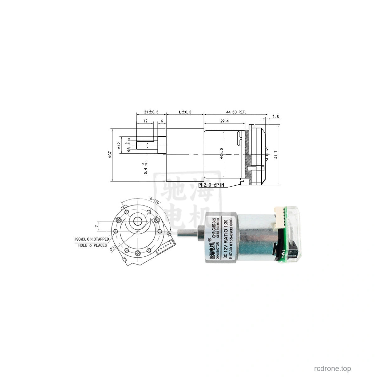
The CHIHAI MOTOR CHR-GM37-3429 DC gear motor combines a37 mm metal reduction gearbox with an AB incremental optical encoder. Select the package,12 V or24 V motor winding, and output speed/ratio independently from the actual available combinations.
Features
- All-metal reduction gears, copper winding and reversible DC operation.
- 6 mm D-shaped output shaft with21 mm projection and12 mm flat length.
- Dual-channel optical encoder for speed and position feedback.
- Five package levels: motor, bracket, flange coupler,65 mm wheel kit or80 mm wheel kit.
What's Included
| Package | Contents |
|---|---|
| Optical encoder motor | 1 geared motor with optical encoder and connection lead |
| Motor and bracket | Motor assembly plus mounting bracket |
| Motor bracket and flange coupler | Motor assembly, bracket and flange coupling |
| 65 mm or80 mm wheel kit | Motor assembly, bracket, hexagonal coupling, selected-diameter wheel and pictured fitting hardware |
Wheel kits use a hexagonal coupling; the separate flange coupling is not substituted into them. Wheel color and tread are not independent selectable options. One motor is included per package; comparison images do not indicate a multi-motor set. A controller and power supply are not included.
Motor Specifications
12 V and24 V are separate selected windings. Their nominal no-load speeds are the same at their respective selected voltages; do not power a12 V winding at24 V. The family reference maximum output power is11 W. Gearbox maximum permitted load is30 kgf·cm (approximately3.0 N·m); stall operation is not a continuous rating.
| Selected ratio / exact reference ratio | No-load rpm,12 or24 V | Rated torque kgf·cm | Rated rpm | Gearbox length mm |
|---|---|---|---|---|
| 6:1 / 6.3:1 | 1550 | 1 | 950 | 19 |
| 10:1 / 10:1 | 1000 | 1.6 | 600 | 19 |
| 18:1 / 18.8:1 | 530 | 3 | 320 | 21.5 |
| 30:1 / 30:1 | 330 | 4.8 | 200 | 21.5 |
| 50:1 / 50:1 | 200 | 8 | 120 | 24 |
| 90:1 / 90:1 | 110 | 14 | 65 | 24 |
| 150:1 / 150:1 | 65 | 24 | 40 | 26.5 |
| 270:1 / 270:1 | 36 | 30 | 27 | 26.5 |
| 450:1 / 450:1 | 22 | 30 | 16 | 29 |
| Electrical reference | 12 V winding | 24 V winding |
|---|---|---|
| No-load current | ≤300 mA | ≤150 mA |
| Rated current, ratios6.3/10/18.8/30/50/90/150/270/450 | ≤2.3/2.3/2.3/2.3/2.3/2.3/2.1/1.9/1.7 A | ≤1.8 A for all ratios |
| Stall current | ≤7.0 A | ≤4.5 A |
| Stall torque, ratios6.3/10/18.8/30/50 | ≥2.5/4.0/7.5/12/20 kgf·cm | ≥2.5/4.0/7.5/12/20 kgf·cm |
| Higher ratios | Observe30 kgf·cm gearbox load limit rather than using a calculated stall figure above it | |
Reference mass is approximately200 g for the motor assembly and varies with gearbox ratio. Dimensions and masses are not identical across all packages.
Optical Encoder and Wiring
Use a separate DC3.3 V or5.0 V encoder supply. The encoder is an AB two-phase incremental optical design with a448 CPR base marking and25–60 kHz response-frequency reference, operating over0–85°C. Output counts per gearbox revolution depend on the selected ratio and decoding convention; calibrate your counting implementation before using position as a measurement.
| Wire color | Signal |
|---|---|
| Red | Encoder B output |
| Black | Encoder A output |
| Green | Encoder GND |
| Blue | Encoder VCC,3.3/5.0 V |
| Yellow | Motor positive |
| White | Motor negative |
The encoder connector is PH2.0-6PIN; the connection lead may terminate in Dupont or XH2.54 style connectors. Confirm actual pin labels before connection; wire colors above apply to the illustrated optical assembly. Never connect motor12/24 V power to encoder VCC, reverse encoder VCC/GND or exceed5 V. Use a microcontroller with a suitable hardware quadrature encoder input, such as STM32. Direct Arduino/8051 decoding is not supported by this configuration guidance.
6 V Series Reference
The following lower-voltage series table is for reference and does not add a6 V winding to the selectable12/24 V options. Reference maximum output is2.6 W, no-load current≤200 mA, rated current≤1.4 A and stall current≤3.5 A.
| Ratio | No-load rpm at6 V | Rated kgf·cm | Rated rpm |
|---|---|---|---|
| 6.3:1 | 775 | 0.5 | 470 |
| 10:1 | 500 | 0.8 | 300 |
| 18.8:1 | 265 | 1.5 | 160 |
| 30:1 | 165 | 2.4 | 100 |
| 50:1 | 100 | 4 | 60 |
| 90:1 | 55 | 7 | 32 |
| 150:1 | 32 | 12 | 20 |
| 270:1 | 18 | 21 | 11 |
| 450:1 | 11 | 30 | 6.5 |
At6 V, stall-torque references for ratios6.3/10/18.8/30/50/90 are≥1.2/2.0/3.7/6.0/10/18 kgf·cm; for higher ratios observe the30 kgf·cm gearbox limit.
Applications and Installation
Suitable for appropriately designed self-balancing vehicles, tracking robots, small mobile platforms, smart appliances, robot mechanisms, pan/tilt mechanisms and electric model assemblies. Match the shaft, mounting pattern, wheel coupling and torque requirement before assembly. Disconnect power before rewiring; avoid continuous stall, overload and unsupported radial loads.
FAQ
Is this a Hall encoder motor?
These selectable packages use an AB incremental optical encoder. Use the optical encoder supply and wiring table above.
Why does the ratio list show6:1 and the reference table6.3:1?
The short selection uses nominal ratio labels; the performance table retains the more precise6.3:1 and18.8:1 references for those two entries.
Visual Details