Kunwei KWR63 Six-Axis Force/Torque Sensor, 63 mm, 50–200 N for Robotics
Kunwei KWR63 Six-Axis Force/Torque Sensor, 63 mm, 50–200 N for Robotics
Kunwei Sensing
Kan de beschikbaarheid voor ophalen niet laden


Overview
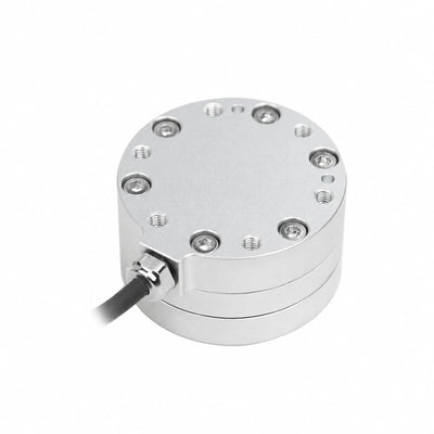
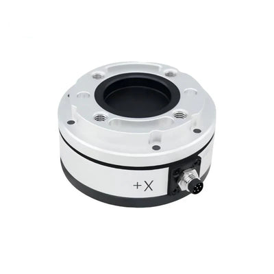
The Kunwei Sensing KWR63 six-axis force/torque sensor measures three forces and three moments for robotic contact control, assembly and multi-axis testing. Its 63 mm diameter, 28 mm high anodized aluminum body fits compact tooling interfaces. Choose KWR63A, B, C or D for rated capacities of 50, 100, 150 or 200 N and 2, 4, 6 or 8 N·m per axis. The documented RS422/RS485 versions include embedded acquisition electronics.
Features
- Simultaneous measurement of Fx, Fy, Fz, Mx, My and Mz using strain-gauge sensing.
- Six-axis joint calibration supports multi-axis measurement with reduced cross-axis interference.
- Four selectable measuring ranges, with the same nominal 63 × 28 mm body size.
- 0.5% FS accuracy, 0.1% FS repeatability and 0.03% FS resolution.
- 300% FS overload level, high rigidity and IP64 protection with correct installation.
- Digital communication options for robotic and industrial measurement integration; interface depends on the acquisition configuration.
Specifications
| Parameter | KWR63A | KWR63B | KWR63C | KWR63D |
|---|---|---|---|---|
| Range Fx, Fy (N) | 50 | 100 | 150 | 200 |
| Range Fz (N) | 50 | 100 | 150 | 200 |
| Range Mx, My (Nm) | 2 | 4 | 6 | 8 |
| Range Mz (Nm) | 2 | 4 | 6 | 8 |
| Diameter (mm) | 63 | 63 | 63 | 63 |
| Height (mm) | 28 | 28 | 28 | 28 |
| Material | Aluminum Alloy | Aluminum Alloy | Aluminum Alloy | Aluminum Alloy |
| Surface Finish | Anodized | Anodized | Anodized | Anodized |
| Overload Level (%FS) | 300 | 300 | 300 | 300 |
| Resolution (%FS) | 0.03 | 0.03 | 0.03 | 0.03 |
| Repeatability (%FS) | 0.1 | 0.1 | 0.1 | 0.1 |
| Accuracy* (%FS) | 0.5 | 0.5 | 0.5 | 0.5 |
| Weight (kg) | 0.12 | 0.14 | 0.16 | 0.18 |
| Protection Rating | IP64 | IP64 | IP64 | IP64 |
| Operating Temperature (°C) | -10~80 | -10~80 | -10~80 | -10~80 |
| Sampling Rate (Hz) | 1000 | 1000 | 1000 | 1000 |
| Supply voltage (VDC) | 9–24 default; 48 only with a specifically rated configuration | 9–24 default; 48 only with a specifically rated configuration | 9–24 default; 48 only with a specifically rated configuration | 9–24 default; 48 only with a specifically rated configuration |
| Communication Interface | RS422 / RS485 / Modbus / CAN / CAN FD / TCP / UDP / EtherCAT / USB; configuration dependent | |||
FS means full scale. Accuracy includes errors from crosstalk, hysteresis and nonlinearity. The capacities apply to individual force and moment axes, not robot payload; include tool mass, lever arms and combined loads in model selection. The overload level does not extend the calibrated measuring range. Body mass is distinct from packed shipping weight.
Use 9–24 VDC as the default supply. The B/C/D family table also lists 12–48 VDC for configured systems, but 48 V requires a specifically rated acquisition configuration; do not apply it to the documented 9–24 V serial version. Some electrical and performance parameters describe the associated acquisition equipment.
The current series specification gives −10 to +80 °C and masses of 0.12/0.14/0.16/0.18 kg. The linked RS422/RS485 revision instead specifies 0 to +80 °C and 0.10/0.10/0.11/0.11 kg. Match the delivered hardware revision; use the serial revision's 0 to +80 °C limit when integrating that version.
Interfaces and Integration
The documented RS422 and RS485 versions process strain-gauge signals with an embedded acquisition system and output digital measurements. The model letter selects the load range; it does not specify or bundle every listed interface. Match the actual output, acquisition equipment and host interface before wiring.
- Documented serial supply: 9–24 VDC; power consumption below 3 W.
- Default serial settings: 460800 baud, 8 data bits, 1 stop bit and no parity.
- RS422 continuous-output command: 0x48 AA 0D 0A, with 1 kHz output; RS485 command and polling behavior differ.
- Measurement frames contain 28 bytes with six floating-point components. Follow the matching manual for byte order and engineering units; its kg/kg·m labels must not be read as N/N·m without the specified conversion.
- RS485 cable: red Power+, black Power−, green A+, white B− and shield. Use the separate RS422 pinout for an RS422 unit.
- Check power polarity before energizing; the documented electronics lack reverse-polarity protection.
- When using an appropriate USB-to-serial adapter, its latency can affect control response; the manual recommends reducing the adapter's default 16 ms latency to 1 ms where supported.
Mechanical Installation
The 28 mm mechanical reference specifies Ø63 ±0.05 mm body diameter, 28 ±0.05 mm height and Ø52 ±0.05 mm mounting pitch circles. It includes face-specific M4 interfaces, 2 × Ø4 pin holes with +0.02/0 tolerance and different 4 mm / 6 mm depths, 0.03 mm datum controls, 24° and 36° spacing and 120° ±0.03° angular references. Use the complete drawing to match each mounting face, hole depth and coordinate direction; do not infer a symmetric or interchangeable interface.
Keep mating surfaces clean and undamaged, position with the locating pins and tighten screws gradually in a diagonal sequence. Do not hammer the sensor into a tight flange, open the sensing body or remove the embedded factory screws. Cable routing must avoid unwanted installation loads. Correct surface contact also matters for IP64 sealing. Allow the documented system to warm up for about 30 minutes and establish zero after installation; account for attached tool weight and orientation.
Applications
- Precision insertion and gearbox assembly: measure contact forces and moments while mating components.
- Curved-surface grinding and precision polishing: provide multi-axis feedback for controlled tool contact.
- Cutting-force measurement and torque-monitoring fixtures within the selected model's load envelope.
- Collaborative robot contact and collision-load research; the sensor alone is not a complete robot safety system.
- Automated vehicle-charging alignment and robotic-arm integration, using the required mounting and communication configuration.
- Sports performance, rehabilitation and medical/surgical robotics research requiring multi-axis load feedback.
- Humanoid, exoskeleton, quadruped and AGV research where the selected loads and mechanical interface fit the installation.
What's Included
- 1 × Kunwei KWR63 sensor in the selected A, B, C or D model.
- 1 × multi-core cable in the documented RS422/RS485 package.
- Electronic user manual and package box.
Power supplies, USB converters, adapter flanges, robot arms and application fixtures are not listed as standard package items. Digital interface availability follows the configured sensor/acquisition system.
Downloads
- KWR63 28 mm mechanical drawing (PDF)
- KWR63 RS485 user manual (PDF)
- KWR63 RS422 user manual (PDF)
- Kunwei six-axis sensor selection manual (PDF)
FAQ
Which KWR63 range should I choose?
A is 50 N / 2 N·m, B 100 N / 4 N·m, C 150 N / 6 N·m and D 200 N / 8 N·m per axis. Check both force and torque, including tool weight and lever-arm moments.
Can I power every version at 48 V?
No. The documented serial versions use 9–24 VDC; 48 V requires a specifically rated acquisition configuration.
Does selecting A, B, C or D select the communication interface?
No. The letter selects the measuring range; match the configured RS422, RS485 or other interface to your host system.
Does this sensor require an external acquisition module?
The documented RS422/RS485 versions have embedded acquisition electronics. Other interface arrangements depend on the supplied configuration; a host adapter or interface converter may still be required.
Can I use any KWR63 mounting drawing?
Use the drawing for the delivered revision. This listing uses the 28 mm body reference; historical 18 mm KWR63 documentation is not an interchangeable mounting specification.
Visual Details