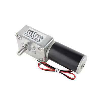
CHIHAI MOTOR CHF-GM3865-520 DC Gear Motor, 6V/12V/24V
CHIHAI MOTOR CHF-GM3865-520 DC Gear Motor, 6V/12V/24V
CHIHAI MOTOR
Teslim alma kullanılabilirliği yüklenemedi


Overview
The CHIHAI MOTOR CHF-GM3865-520 is a permanent-magnet brushed DC gear motor with a flat metal gearbox and 6 mm D-shaped output shaft. Select the motor winding,nominal ratio and accessory package. Available selections use a forward output shaft;the reverse-side installation and encoder-equipped illustrations below are mounting references.
Features
- Metal reduction gears in an L-shaped assembly.
- 6 mm D-shaft with 23.5 mm projection and 12 mm flat-length references.
- 6V0630,12V1260 and 24V motor selections where available.
- Optional bracket,PWM/digital/reversing controllers,power supply,gear or flange-coupler packages.
Specifications
| Specification | Value / scope |
|---|---|
| Brand/model | CHIHAI MOTOR CHF-GM3865-520 permanent-magnet brushed DC gearmotor |
| Selectable windings | 6V0630,12V1260 and 24V;check actual retained package/ratio combination |
| Selected output configuration | Forward output shaft;reverse-side illustration is a separate mounting reference |
| Nominal ratio options | 42:1,67:1,125:1,225:1,450:1 |
| Body reference | L-shaped38×64.5×40 mm |
| Gearbox drawing envelope | 38±0.3×64.4±0.3 mm |
| Output shaft | 6 mm diameter;5.4(+0/−0.1)mm D-flat;23.5±0.5 mm projection;12 mm flat length |
| Mounting references | Four M3 rear mounting-hole callout;4×3.1 and 4×3.3 mm drawing apertures;26.5±0.3×50±0.3 mm hole-pattern references |
| Other drawing references | 12 mm register;3 mm step;1.70 mm shoulder reference;31 mm motor-axis offset;33 mm motor diameter;7.5 mm rear register;0.5/3/6.5/22.5/11.80 mm axial references |
| Motor weight | Approximately165 g;varies by ratio |
| Gear construction | Metal reduction gears |
| Bracket | Carbon steel,black coated;approximately 53 g with mounting screws |
| Bracket drawing | 64.3 mm width;43.5 mm upright;20.7 mm base;2 mm thickness;49.8 mm hole spacing;26.4/11.4/7.2 mm references;14.5 mm apertures;four3.1 mm holes;3.2/14/9.2/8 mm base references |
| PWM controller reference | 2.2–12V DC input for the illustrated small controller;not a 24V controller |
| Wheel/gear/coupler dimensions | Use the pictured package and actual fit;no unsupported tooth count,bore or pitch supplied |
Performance by Winding
The nominal 67:1 selector corresponds to the 67.5:1 table reference. Keep each winding's current,speed and torque data separate. The24V2473 table instead lists135:1 in its third column;that column is a separate reference and must not be assigned to the selectable 125:1 option. The24V selection itself does not state a winding code. The6V0660 and 3V0330 tables are additional family references,not selectable windings here.
6V0630
Maximum power reference 0.6W;no-load current ≤50mA.
| Table ratio | No-load rpm | Rated torque(kgf·cm) | Rated rpm | Rated current(A) | Stall current(A) | Stall torque / limit(kgf·cm) |
|---|---|---|---|---|---|---|
| 42:1 | 75 | 1.00 | 47 | ≤0.35 | ≤0.85 | ≥2.5 |
| 67.5:1 | 46 | 1.50 | 30 | ≤0.35 | ≤0.85 | ≥4.0 |
| 125:1 | 25 | 3.00 | 16 | ≤0.35 | ≤0.85 | ≥7.0 |
| 225:1 | 14 | 5.50 | 8 | ≤0.35 | ≤0.85 | ≥12.0 |
| 450:1 | 7 | 10.00 | 4.5 | ≤0.35 | ≤0.85 | ≥22.0 |
12V1260
Maximum power reference 2.3W;no-load current ≤65mA.
| Table ratio | No-load rpm | Rated torque(kgf·cm) | Rated rpm | Rated current(A) | Stall current(A) | Stall torque / limit(kgf·cm) |
|---|---|---|---|---|---|---|
| 42:1 | 150 | 2.00 | 95 | ≤0.7 | ≤1.7 | ≥5.0 |
| 67.5:1 | 92 | 3.00 | 60 | ≤0.7 | ≤1.7 | ≥8.0 |
| 125:1 | 50 | 6.00 | 32 | ≤0.7 | ≤1.7 | ≥14.0 |
| 225:1 | 28 | 11.00 | 17 | ≤0.7 | ≤1.7 | Maximum25 |
| 450:1 | 14 | 20.00 | 9 | ≤0.7 | ≤1.7 | Maximum25 |
24V2473 reference
Maximum power reference 3.0W;no-load current ≤100mA.
| Table ratio | No-load rpm | Rated torque(kgf·cm) | Rated rpm | Rated current(A) | Stall current(A) | Stall torque / limit(kgf·cm) |
|---|---|---|---|---|---|---|
| 42:1 | 170 | 2.0 | 105 | ≤0.35 | ≤1.30 | ≥5.0 |
| 67.5:1 | 105 | 3.0 | 65 | ≤0.35 | ≤1.30 | ≥8.0 |
| 135:1 | 54 | 6.0 | 33 | ≤0.35 | ≤1.30 | ≥15.0 |
| 225:1 | 32 | 11.0 | 21 | ≤0.35 | ≤1.30 | Maximum25 |
| 450:1 | 16 | 20.0 | 10 | ≤0.35 | ≤1.30 | Maximum25 |
Additional 24V rated-torque references in N·m:0.2,0.3,0.6,1.1,2.0 in the same column order.
6V0660 series reference
Maximum power reference 1.7W;no-load current ≤100mA.
| Table ratio | No-load rpm | Rated torque(kgf·cm) | Rated rpm | Rated current(A) | Stall current(A) | Stall torque / limit(kgf·cm) |
|---|---|---|---|---|---|---|
| 42:1 | 150 | 2.00 | 75 | ≤0.7 | ≤2.4 | ≥5.0 |
| 67.5:1 | 92 | 3.00 | 45 | ≤0.7 | ≤2.4 | ≥8.0 |
| 125:1 | 50 | 6.00 | 25 | ≤0.7 | ≤2.4 | ≥14.0 |
| 225:1 | 28 | 11.00 | 14 | ≤0.7 | ≤2.4 | Maximum25 |
| 450:1 | 14 | 20.00 | 7 | ≤0.7 | ≤2.4 | Maximum25 |
3V0330 series reference
Maximum power reference 0.5W;no-load current ≤50mA.
| Table ratio | No-load rpm | Rated torque(kgf·cm) | Rated rpm | Rated current(A) | Stall current(A) | Stall torque / limit(kgf·cm) |
|---|---|---|---|---|---|---|
| 42:1 | 75 | 1.00 | 37 | ≤0.35 | ≤1.2 | ≥2.5 |
| 67.5:1 | 46 | 1.50 | 23 | ≤0.35 | ≤1.2 | ≥4.0 |
| 125:1 | 25 | 3.00 | 12 | ≤0.35 | ≤1.2 | ≥7.0 |
| 225:1 | 14 | 5.50 | 7 | ≤0.35 | ≤1.2 | ≥12.0 |
| 450:1 | 7 | 10.00 | 4 | ≤0.35 | ≤1.2 | ≥22.0 |
Maximum-power figures describe separate operating points,not continuous rated output for every ratio. For the 12V1260,24V2473 and 6V0660 high-ratio tables,the merged25 kgf·cm cells state a maximum permissible gearbox load,not guaranteed stall torque. Avoid prolonged stalling,overload and repeated reversing starts.
Mounting and Controller Selection
Check the complete drawing and actual package before installation. The nominal 38×64.5×40 mm envelope and precise38±0.3×64.4±0.3 mm gearbox drawing are distinct references. Confirm shaft,front/rear mounting interfaces and bracket clearance. Multiple bracket mounting positions are illustrated. The two-motor drawings show approximately 95 mm width for opposed same-axis mounting or approximately 48 mm width and 105 mm height for offset mounting. These are multi-motor layout references;each product selection includes one motor. Encoder-equipped reference photos do not add an encoder to the selected motor.
Use DC voltage matching the selected winding. The pictured small PWM board has a 2.2–12V DC input reference and must never be connected directly to 220V AC. It is not specified for 24V operation. Check polarity at the controller's supply input and follow its actual terminal markings. Match digital and reversing controller ratings to the actual supply,motor current and load before wiring.
Power-supply packages:the package photographs identify a 12V adapter,including shared photographs used for 6V selections. Do not connect12V directly to a 6V motor. A6V selection needs a correctly rated6V supply or a verified voltage-control arrangement. A speed-controller package name alone does not confirm voltage conversion or a safe6V motor setting. Check the supplied adapter output and controller arrangement before use.
Applications
Compatible smart kitchen mechanisms,small rotating barbecue racks,sunshade mechanisms and smart-curtain drives. Check required load,ratio,supply and mechanical fit. Speed changes with load;avoid stalled or overloaded operation.
What's Included
| Selected package | Contents |
|---|---|
| Motor Only | 1 motor |
| Motor + Mounting Bracket | 1 motor,1 bracket and mounting screws |
| Motor + PWM Speed Controller | 1 motor and 1 small PWM controller |
| Motor + Bracket + PWM Controller | 1 motor,1 bracket with screws and 1 small PWM controller |
| Motor + 12V Supply + Bracket | 1 motor,1 bracket with screws and 1 pictured12V power-supply assembly |
| Motor + 12V Supply + PWM Controller + Bracket | 1 motor,1 bracket with screws,1 pictured12V supply and 1 small PWM controller |
| Motor + 12V Supply + Forward/Reverse Controller | 1 motor,1 pictured12V supply and 1 forward/reverse controller assembly |
| Motor + Digital Speed Controller + Bracket | 1 motor,1 bracket with screws and 1 digital speed-controller assembly |
| Motor + Bracket + Large Gear | 1 motor,1 bracket with screws and 1 large gear |
| Motor + Bracket + Flange Coupler | 1 motor,1 bracket with screws and 1 flange coupler with shown fastening hardware |
Only the selected package's accessories are included. A motor-only selection does not include a bracket,controller,power adapter,encoder,large gear or flange coupler. Photo labels are shared package references;the actual motor winding and ratio follow the selected option.
FAQ
Can the 12V adapter be connected directly to a 6V motor?
No. Match the motor voltage using a correct 6V supply or a verified voltage-control arrangement. Confirm the actual controller settings and output before connection.
Does this listing include the reverse-side shaft or an encoder?
The selectable shaft orientation is forward. Reverse-side and encoder-equipped photos are installation references and do not change the selected configuration.
Does the 24V135:1 table describe my125:1 option?
No. The third24V table column is marked135:1. No125:1 performance value is inferred from it.
Is25 kgf·cm a guaranteed high-ratio stall torque?
No. The merged high-ratio table entries state a maximum permissible load;avoid stalling and overload.
Does the bracket package include two motors?
No. Each selection includes one motor. The two-motor drawings illustrate possible layouts only.
Visual Details