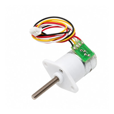
CHIHAI CHS-GM37BY-58 M6 Screw Shaft Stepper Motor, 10:1
CHIHAI CHS-GM37BY-58 M6 Screw Shaft Stepper Motor, 10:1
CHIHAI MOTOR
Teslim alma kullanılabilirliği yüklenemedi


Overview
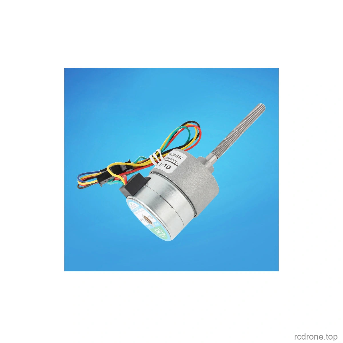
The CHIHAI MOTOR CHS-GM37BY-58 M6 is a two-phase, four-wire geared stepper motor with a 58 mm M6 threaded output shaft and a fixed 10:1 reduction. Choose the motor alone or add a mounting bracket, a matching flange nut, or both for compact screw-driven positioning mechanisms.
Features
- M6 × 1.0 threaded shaft with 58 ±0.5 mm projection.
- Metal reduction gears and reversible step motion through a compatible bipolar stepper driver.
- 7.5° motor full step and 0.75° nominal output full step at 10:1 reduction.
- Four real package choices, each with its own component photograph.
Specifications
| Parameter | Value |
|---|---|
| Brand / model | CHIHAI MOTOR / CHS-GM37BY-58 M6 |
| Motor type | Two-phase, four-wire bipolar stepper with metal reduction gears |
| Reduction ratio | 10:1, fixed for all packages offered here |
| Motor rated reference | 12 V DC; 0.4 A per phase |
| Phase resistance | 30 Ω ±15% |
| Motor / output full-step angle | 7.5° / 0.75°; not a positioning-accuracy guarantee |
| Screw shaft | M6 × 1.0; 58 ±0.5 mm shaft projection |
| Gearbox / rear body diameter | 37 mm / 35 mm, see drawing |
| Gearbox length L | 19.0 mm at 10:1; drawing tolerance ±0.3 mm |
| Motor body length reference | 22.2 mm maximum, see drawing |
| Mounting | Six M3.0 × 3 tapped holes; see original front-view geometry |
| Cable / connector | UL1007 AWG26; 150 ±10 mm lead; SM-4PIN |
| Motor mass | Approximately 165–200 g, source series reference |
| Input motor pull-out / holding torque | At least 300 gf·cm / at least 600 gf·cm at 0 PPS |
| Maximum response / starting frequency | 750 PPS/Hz / 700 PPS/Hz source reference |
| Insulation | Class E coils; 100 MΩ at 500 V DC; 100 V AC for one second dielectric reference |
| Operating temperature | −10 to +55°C |
Wiring and Operation
Use a compatible two-phase bipolar stepper driver and a pulse/control source. The 12 V motor reference and the 3.7–24 V source drive tests are distinct from a driver supply specification. Set suitable phase-current limits and check temperature under the actual load; do not connect the windings directly to a DC supply. Disconnect power before changing wiring.
| Connector pin | Wire | Phase |
|---|---|---|
| 1 | Yellow | A |
| 2 | Black | B |
| 3 | Red | B− |
| 4 | Green | A− |
Yellow and green form one phase; black and red form the other. Check connector orientation against the diagram. Avoid overloads, sustained stalls, resonance and repeated blocking. Operating sound varies with pulse rate and load. Holding torque is a stationary value and must not be treated as continuous running torque.
Output Performance Reference
Only 10:1 is sold here. The following source family data distinguish test conditions and other ratios; those other ratios are comparison references, not additional selectable configurations. The source limits gearbox torque to 30 kgf·cm. Test speed depends on drive pulses and load.
12 V DC test
Source condition: 400 PPS/Hz, input motor 500 RPM.
| Ratio | L (mm) | Output step (°) | No-load RPM | Holding (kgf·cm) | Pull-out (kgf·cm) |
|---|---|---|---|---|---|
| 6.3:1 | 19 | 1.19 | 79 | 2.8 | 1.2 |
| 10:1 — sold here | 19 | 0.75 | 50 | 4.5 | 2 |
| 18.8:1 | 21.5 | 0.399 | 26 | 8 | 3.5 |
| 30:1 | 21.5 | 0.25 | 16 | 13 | 6 |
| 50:1 | 24 | 0.15 | 10 | 22 | 10 |
| 67:1 | 24 | 0.112 | 7 | 30 | 13 |
| 90:1 | 24 | 0.083 | 5.5 | Max 30 | 18 |
| 150:1 | 26.5 | 0.05 | 3.3 | Max 30 | Max 30 |
| 270:1 | 26.5 | 0.027 | 1.9 | Max 30 | Max 30 |
| 450:1 | 29 | 0.0167 | 1.1 | Max 30 | Max 30 |
| 630:1 | 29 | 0.012 | 0.8 | Max 30 | Max 30 |
| 810:1 | 29 | 0.0093 | 0.6 | Max 30 | Max 30 |
24 V DC test
Source condition: 600 PPS/Hz, input motor 750 RPM.
| Ratio | L (mm) | Output step (°) | No-load RPM | Holding (kgf·cm) | Pull-out (kgf·cm) |
|---|---|---|---|---|---|
| 6.3:1 | 19 | 1.19 | 119 | 3.5 | 2 |
| 10:1 — sold here | 19 | 0.75 | 75 | 5.5 | 3.2 |
| 18.8:1 | 21.5 | 0.399 | 40 | 10 | 5.8 |
| 30:1 | 21.5 | 0.25 | 25 | 16.5 | 9 |
| 50:1 | 24 | 0.15 | 15 | 25 | 15 |
| 67:1 | 24 | 0.112 | 11 | Max 30 | 20 |
| 90:1 | 24 | 0.083 | 8.3 | Max 30 | 28 |
| 150:1 | 26.5 | 0.05 | 5 | Max 30 | Max 30 |
| 270:1 | 26.5 | 0.027 | 2.7 | Max 30 | Max 30 |
| 450:1 | 29 | 0.0167 | 1.7 | Max 30 | Max 30 |
| 630:1 | 29 | 0.012 | 1.2 | Max 30 | Max 30 |
| 810:1 | 29 | 0.0093 | 0.9 | Max 30 | Max 30 |
The dimension drawing groups a nominal 70:1 gearbox while the performance table lists 67:1; both are family references. This difference does not affect the fixed 10:1 package sold here.
Drive and Resonance Test Reference
The following source measurements used a stepper tester and full-step excitation without current limiting. They are operating-window references, not continuous phase-current recommendations. Use current limiting, thermal checks and a pulse rate that avoids resonance.
| Test DC supply | Upper Hz / test current | Input RPM | Lower Hz / test current | Input RPM | Locked current, 0 Hz |
|---|---|---|---|---|---|
| 24 V | 670 / ≤0.12 A | 837.5 | 550 / ≤0.16 A | 687.5 | 1.5 A |
| 12 V | 460 / ≤0.07 A | 575 | 330 / ≤0.10 A | 412.5 | 0.78 A |
| 6 V | 280 / ≤0.06 A | 350 | 200 / ≤0.16 A | 250 | 0.4 A |
| 3.7 V | 150 / ≤0.06 A | 187.5 | 60 / ≤0.15 A | 75 | 0.25 A |
Mechanical Installation and Applications
The threaded shaft and optional flange nut suit compact screw-driven positioning, camera-motion mechanisms, smart appliances and robotics projects. Confirm travel, alignment, axial/radial load capacity and end stops for the actual mechanism; the source does not specify an allowable linear load. Use the original dimension drawings to check clearances. The optional bracket has a 40 mm base width, 47 mm height, 43 mm side-view depth and 3 mm thickness. The flange nut uses an M6 × 1.0 internal thread and four 3 mm mounting holes on the shown 16 mm spacing; see its drawing for the complete dimensions.
What's Included
| Package | Contents |
|---|---|
| Motor Only | 1 × motor |
| Motor + Bracket | 1 × motor; 1 × mounting bracket |
| Motor + Flange Nut | 1 × motor; 1 × M6 flange nut |
| Motor + Bracket + Flange Nut | 1 × motor; 1 × mounting bracket; 1 × M6 flange nut |
All packages use the 10:1 gearbox and 58 mm M6 shaft. Driver, power supply, pulse controller and application mechanism are not included.
FAQ
Can I choose a different reduction ratio?
No. This listing offers only 10:1. Other ratios in the family reference tables are not selectable.
Does the motor run when connected directly to 12 V?
No. It needs a compatible bipolar stepper driver and control pulses. Verify phase-current settings and wiring before operation.
Is the flange nut included with every package?
No. Select Motor + Flange Nut or Motor + Bracket + Flange Nut to receive it.
Visual Details