CHIHAI GM37-BLDC3525 Brushless DC Gear Motor with Built-in Driver
CHIHAI GM37-BLDC3525 Brushless DC Gear Motor with Built-in Driver
CHIHAI MOTOR
Teslim alma kullanılabilirliği yüklenemedi


Overview
The CHIHAI MOTOR CHR-GM37-BLDC3525 is a 37 mm brushless DC gear motor with an internal Hall driver, all-metal reduction gears and a 6 mm D-shaped output shaft. Choose 12V or 24V, the reduction ratio and a motor-only, bracket or PWM-controller package.
Features
- Internal brushless commutation driver for direct matched DC power.
- Separate direction and speed-control inputs with FG speed feedback.
- All-metal gear train and D-shaped shaft for compact motion mechanisms.
- Selectable external PWM controller and mounting bracket packages.
Specifications
| Item | Specification |
|---|---|
| Model | CHR-GM37-BLDC3525 (also CHR-GM37-BL3525) |
| Motor | Permanent-magnet brushless DC, six-slot rotor, built-in Hall driver |
| Voltage choices | 12V DC or 24V DC; select the matching winding, not interchangeable |
| Gearbox | 37 mm diameter, all-metal gears; gearbox length varies with ratio |
| Output shaft | 6 mm D-shaft; 21 mm projection, 12 mm flat length, 5.4 mm flat dimension |
| Motor body | 35.2 mm diameter; 21.8 mm length behind gearbox |
| Mounting | Six M3 tapped holes, 3 mm depth, on 31 mm pitch circle; confirm orientation before machining |
| Net motor mass | Approximately 160-180 g depending on ratio |
| Lead length | 250 mm drawing reference |
| Drive | Internal Hall commutation; DC power does not require an external three-phase BLDC driver |
| Direction | White CW/CCW input: open = one direction; connect to GND = opposite direction |
| Speed input | Blue PWM/control lead: 0-5V input range; analog regulation reference 1.2-3.3V |
| Feedback | Yellow FG open-collector output, 9 pulses per motor-shaft revolution; max sink current 5 mA |
| FG logic | With 5V / 10 kohm pull-up: high >=4V, low <=0.6V |
| Direction logic reference | 0-5V input; VIH >=2V, VIL <=0.2V. Use matching wiring reference. |
| Package | One motor; optional bracket and/or PWM controller only as selected |
Ratio and Dimensions
Selector ratios 6:1 and 18:1 correspond to the 6.3:1 and 18.8:1 performance references. Other ratio labels match the reference columns. FG counts refer to motor rotation multiplied by the actual gearbox ratio.
| Reference ratio | Gearbox length L (mm) | FG pulses per output revolution |
|---|---|---|
| 6.3 | 19 | 56.7 |
| 10 | 19 | 90 |
| 18.8 | 21.5 | 169.2 |
| 30 | 21.5 | 270 |
| 50 | 24 | 450 |
| 90 | 24 | 810 |
| 150 | 26.5 | 1350 |
| 260 | 26.5 | 2340 |
| 450 | 29 | 4050 |
| 630 | 29 | 5670 |
Electrical Performance
Rated torque, holding torque and stall current describe different conditions. Holding torque is not a continuous running rating or payload capacity. Independently rounded kgf·cm and N·m values are retained as reference data.
24V
Maximum output-power reference 8 W; no-load current ≤130 mA; rated current ≤0.40 A. Stall current ≤3.0 A. Avoid repeated starts or continuous direction reversals.
| Ratio | No-load rpm | Rated kgf·cm | Rated N·m | Rated rpm | Holding kgf·cm (minimum) |
|---|---|---|---|---|---|
| 6.3:1 | 930 | 0.9 | 0.09 | 700 | 2 |
| 10:1 | 585 | 1.4 | 0.14 | 445 | 3.5 |
| 18.8:1 | 310 | 2.5 | 0.25 | 235 | 6.5 |
| 30:1 | 195 | 4 | 0.4 | 145 | 10 |
| 50:1 | 117 | 7 | 0.7 | 85 | 15 |
| 90:1 | 65 | 12 | 1.2 | 48 | 25 |
| 150:1 | 39 | 21 | 2.1 | 29 | 30 |
| 260:1 | 23 | 30 | 3 | 17 | 30 |
| 450:1 | 13 | 30 | 3 | 9 | 30 |
| 630:1 | 9 | 30 | 3 | 6 | 30 |
12V
Maximum output-power reference 2 W; no-load current ≤100 mA; rated current ≤0.30 A. Stall current ≤3.0 A. Avoid repeated starts or continuous direction reversals.
| Ratio | No-load rpm | Rated kgf·cm | Rated N·m | Rated rpm | Holding kgf·cm (minimum) |
|---|---|---|---|---|---|
| 6.3:1 | 465 | 0.4 | 0.04 | 330 | 1 |
| 10:1 | 290 | 0.7 | 0.07 | 220 | 1.7 |
| 18.8:1 | 155 | 1.2 | 0.12 | 115 | 3 |
| 30:1 | 95 | 2 | 0.2 | 72 | 5 |
| 50:1 | 57 | 3.5 | 0.35 | 42 | 7 |
| 90:1 | 32 | 6 | 0.6 | 24 | 12 |
| 150:1 | 20 | 10 | 1 | 14 | 15 |
| 260:1 | 11 | 15 | 1.5 | 8 | 20 |
| 450:1 | 6 | 25 | 2.5 | 4 | 30 |
| 630:1 | 4.5 | 30 | 3 | 3 | 30 |
Wiring and Control
Red is motor VCC; black is GND. Match power to the selected 12V or 24V motor and never reverse supply polarity. White is CW/CCW direction, blue is PWM/speed control, and yellow is FG speed output. The detailed VCC ±10% reference in the wiring table is for the 12V version; it does not make a 12V motor compatible with 24V.
White left open selects one rotation direction; connecting white to black reverses it. The logic table labels high as CCW and low as CW; confirm viewing direction on the actual mechanism before commissioning. Speed can be regulated through the blue control lead. The 0-5V control-input range and 1.2-3.3V analog regulation reference are distinct; no PWM frequency is specified.
FG provides 9 pulses per motor revolution, not 9 per gearbox-output revolution. Use an external pull-up and compatible counter; do not apply motor voltage to the FG signal.
Optional PWM Controller
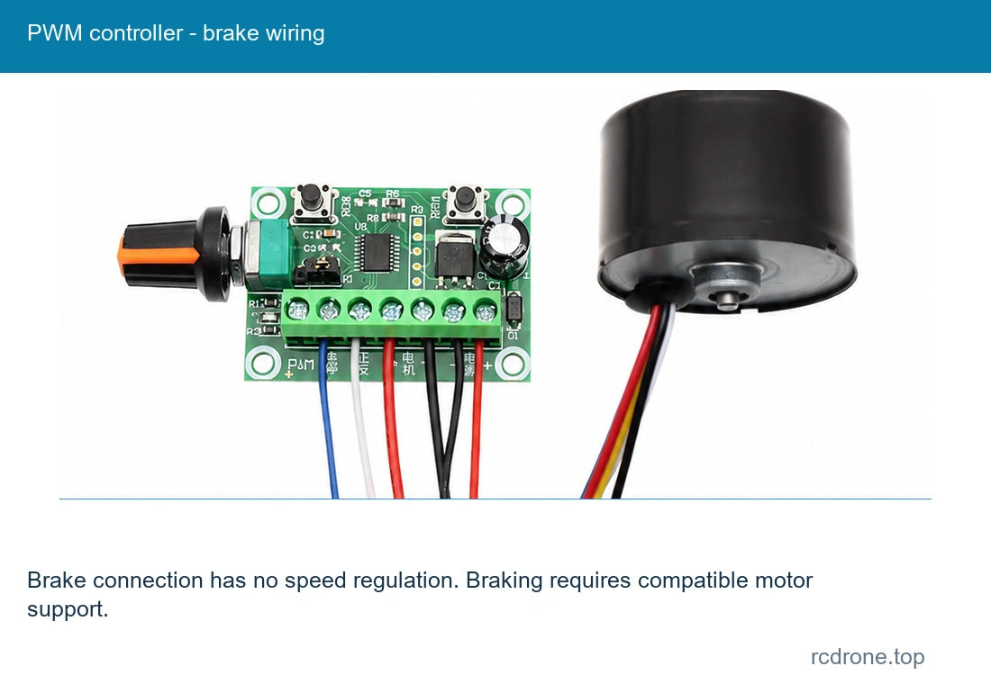
The controller package includes one external control board with a speed knob. Its wiring sheet specifies a DC 6-30V controller input; the motor itself must still receive its selected nominal voltage. Never connect AC mains. The illustrated speed-control and brake connections are alternative arrangements; the brake arrangement has no speed regulation. Braking and direction functions require compatible motor support. Connect to the printed terminal labels and verify the selected wiring before powering.
Applications
- Compact robot and machinery drives using speed feedback.
- Smart home mechanisms, powered doors and windows.
- Automatic rotation fixtures and pan/tilt motion within the selected motor ratings.
What's Included
Motor Only: one motor with its attached five-wire lead set. Motor + Bracket: one motor and one mounting bracket. Motor + PWM Controller: one motor and one controller board. Motor + PWM Controller + Bracket: one of each. Power supply, feedback counter, complete robot and application machinery are not included.
Installation and Operation
Check shaft, mounting-hole orientation and gearbox length for the selected ratio. Avoid overload, stall, forceful shaft rotation and continuous reversing. This motor contains its driver: incorrect wiring can damage it. Rotation speed falls with load and acoustic noise varies with operating conditions.
FAQ
Does the motor need an external three-phase BLDC driver?
No. Hall commutation and the driver are internal. The optional board provides external control functions.
Can a 12V motor be powered from 24V?
No. Choose and power the correct voltage version.
Is FG resolution 9 pulses at the output shaft?
No. It is 9 pulses per motor revolution; multiply by the actual reduction ratio for output-shaft feedback.
Does every package include a PWM controller?
No. Only packages naming the controller include it; bracket inclusion is also selected separately.
Visual Details