ESP32-S3 Wi-Fi & BLE Development Board, N8R2 / N8R8 / N16R8
ESP32-S3 Wi-Fi & BLE Development Board, N8R2 / N8R8 / N16R8
Your Cee
Teslim alma kullanılabilirliği yüklenemedi


Overview
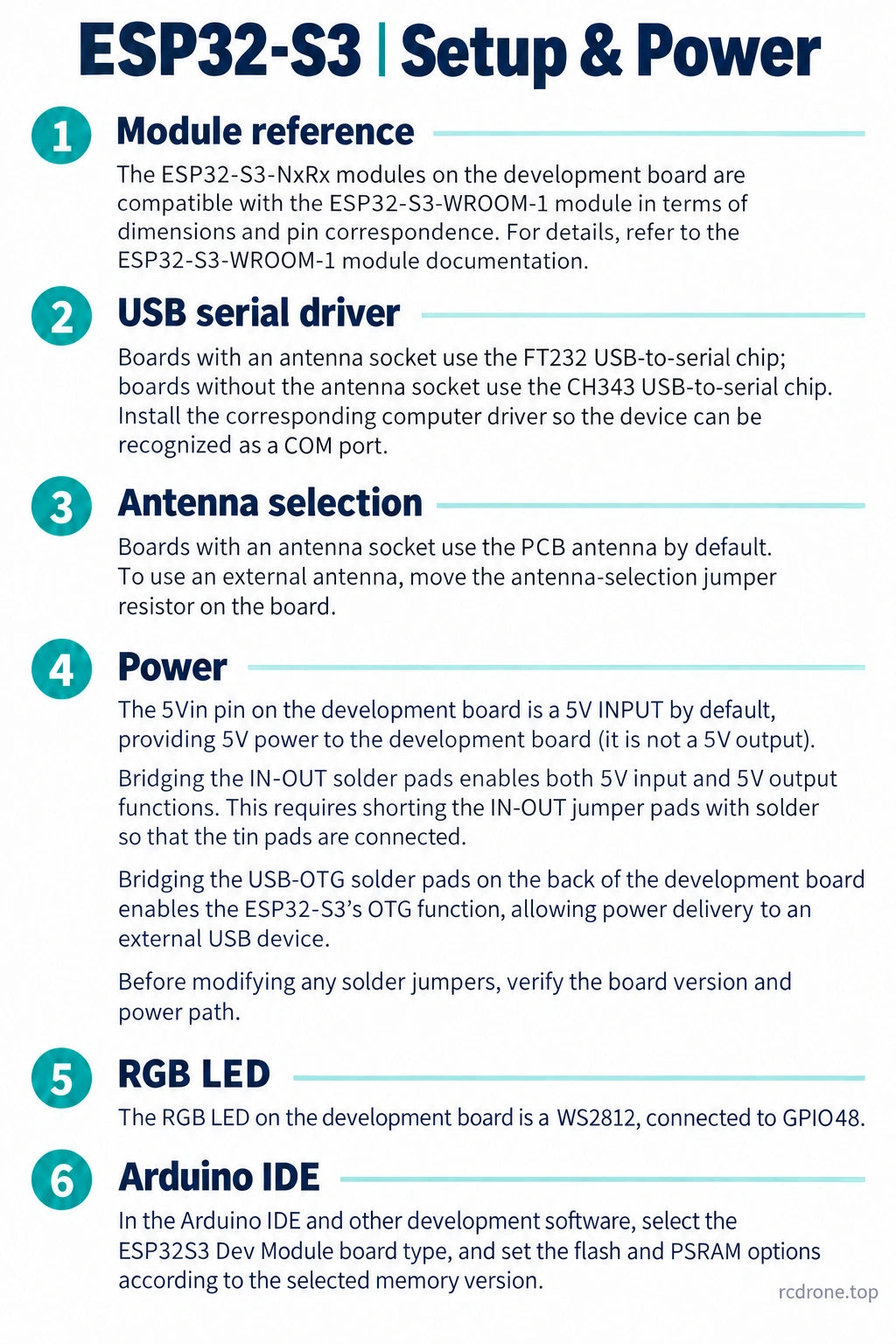
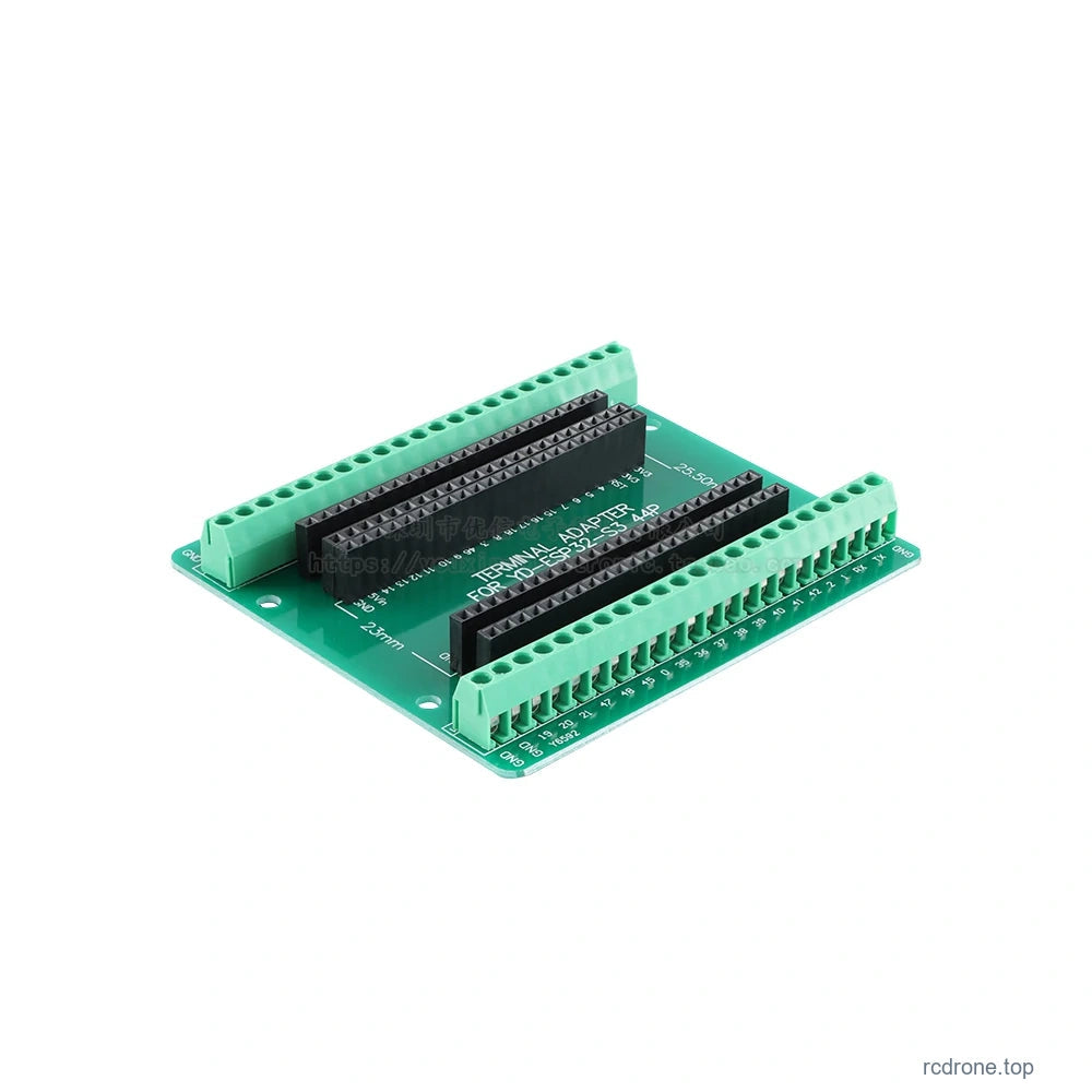
This ESP32-S3 microcontroller board combines a dual-core 32-bit processor with 2.4 GHz Wi-Fi and Bluetooth Low Energy for connected embedded projects. Choose N8R2, N8R8 or N16R8 memory, soldered or unsoldered pin headers, and an antenna-socket version where listed. The green 44-pin breakout board is a separate accessory option and does not include an ESP32-S3 development board.
Features
- Up to 240 MHz dual-core Xtensa LX7 processing with vector and DSP instructions for embedded AI workloads.
- Three flash/PSRAM configurations to match firmware and buffer requirements.
- USB programming, native USB functionality and common serial interfaces for peripheral integration.
- WS2812 addressable RGB LED on GPIO48.
- Choose pre-soldered headers for convenient connection or loose headers for assembly.
Specifications
| Processor | Dual-core 32-bit Xtensa LX7, up to 240 MHz; vector and DSP instructions |
|---|---|
| Internal memory | 512 KB SRAM |
| N8R2 memory | 8 MB flash + 2 MB PSRAM |
| N8R8 memory | 8 MB flash + 8 MB PSRAM |
| N16R8 memory | 16 MB flash + 8 MB PSRAM |
| Wi-Fi | 2.4 GHz IEEE 802.11 b/g/n |
| Bluetooth | Bluetooth 5 Low Energy (BLE) |
| Serial and peripheral interfaces | 3 UART controllers; SPI, I2C, I2S, PWM; LCD and LED control peripherals |
| ADC | 12-bit conversion; available inputs depend on board routing and selected module |
| USB | Native USB 2.0 full-speed, OTG and CDC capabilities; board solder-jumper conditions apply |
| USB-to-serial chip | FT232 on antenna-socket versions; CH343 on versions without an antenna socket |
| RGB LED | WS2812 connected to GPIO48 |
| Power input | 5V at 5Vin, or regulated 3.3V at the appropriate supply pin; onboard LDO |
| Headers | Soldered or unsoldered as selected |
| Breakout accessory | Green 44-pin terminal breakout board, sold separately as a board-only option |
Peripheral availability depends on module memory use and board routing. The ESP32-S3 chip has up to 45 programmable GPIOs; this is not a promise of 45 freely available pins on every board configuration.
Configuration Guide
N8R2 provides 8 MB flash and 2 MB PSRAM; N8R8 provides 8 MB flash and 8 MB PSRAM; N16R8 provides 16 MB flash and 8 MB PSRAM. Only the N8R2 and N16R8 configurations listed with an antenna socket include that connector. Socket versions use the PCB antenna by default; changing to an external antenna requires repositioning the antenna-selection jumper resistor.
Power and USB Setup
The 5Vin pin is a 5V input by default. To enable input/output operation, bridge the IN-OUT solder pads. Bridging the rear USB-OTG solder pads enables power delivery to an attached USB peripheral for OTG use. Verify the selected board and its power path before modifying solder jumpers. Install the matching FT232 or CH343 computer driver for USB serial communication.
Development Software
In Arduino IDE, select ESP32S3 Dev Module and match the flash and PSRAM settings to the selected memory configuration. The module dimensions and pin correspondence follow the ESP32-S3-WROOM-1 reference; check the actual board and module documentation before designing a carrier or enclosure.
Applications
- Wi-Fi-connected sensors and IoT prototypes.
- Bluetooth Low Energy peripheral projects.
- Embedded control, peripheral interfaces and small robotics prototypes.
- Embedded AI and voice-interaction development where the chosen firmware, memory and external hardware are suitable.
What's Included
- Development-board option: one selected ESP32-S3 board with soldered headers, or the loose headers shown for the unsoldered option.
- 44-pin breakout-board option: one green breakout board only; ESP32-S3 processor board not included.
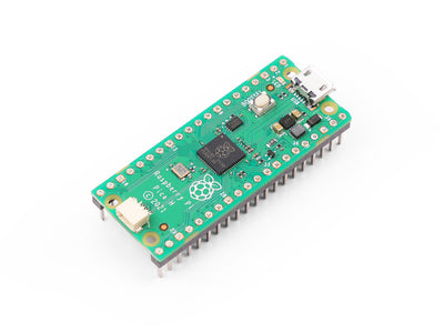
Comparison photos show configuration alternatives, not a two-board package. USB cable, external antenna, display, microphone, speaker, battery and robot hardware are not included.
FAQ
Does the green breakout option include an ESP32-S3 board?
No. It is the terminal breakout board only; select a development-board option separately if needed.
Is the antenna socket active by default?
No. Socket versions use the PCB antenna initially. External-antenna use requires changing the antenna-selection jumper resistor.
Can I use 5Vin as a 5V output immediately?
The pin is an input by default. Input/output operation requires bridging the IN-OUT solder pads after checking the board power path.
Which Arduino board profile should I choose?
Select ESP32S3 Dev Module, then set flash and PSRAM to match N8R2, N8R8 or N16R8.
Visual Details