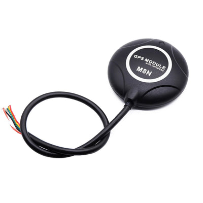
Beitian BE-245 M10050 GNSS 定位模組,內建天線,TTL NMEA/UBX 適用於固定翼
Beitian BE-245 M10050 GNSS 定位模組,內建天線,TTL NMEA/UBX 適用於固定翼
Beitian
正常價格
$29.66 USD
正常價格
銷售價格
$29.66 USD
單價
每
含稅。
船運 結帳時計算。
無法載入取貨情況


概述
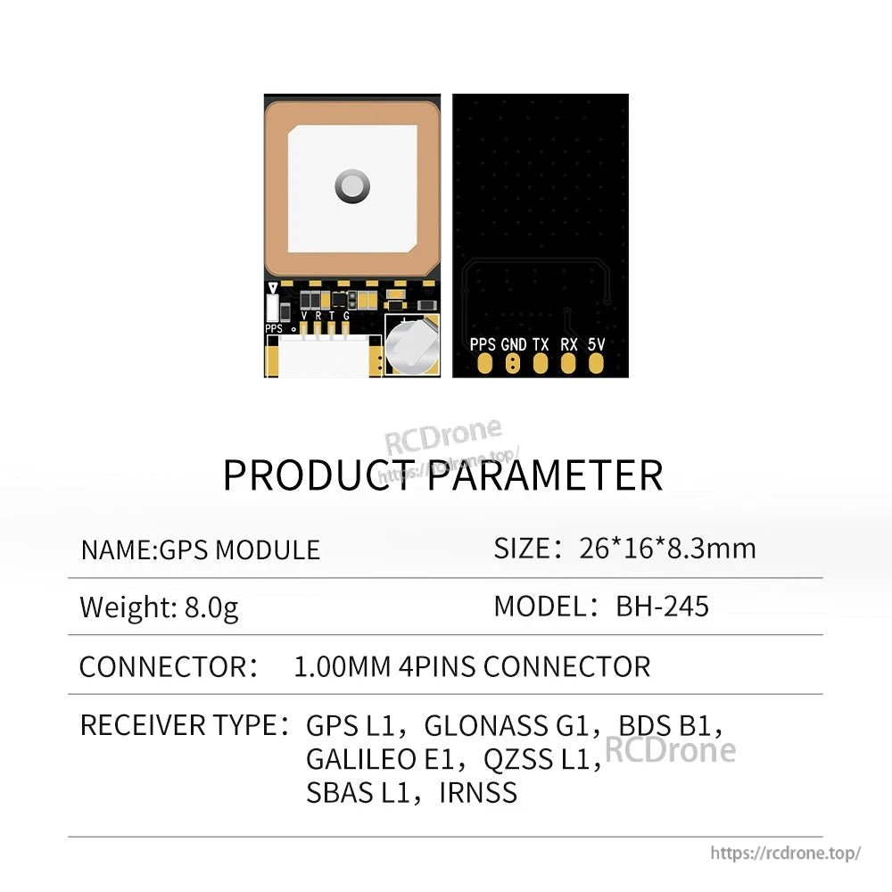
Beitian BE-245 是一款具備內建定時天線的 GNSS 定位模組,專為固定翼及其他嵌入式導航應用設計,要求緊湊尺寸和 TTL 串行輸出。它支持多個 GNSS 星座在 L1 上,並通過 NMEA/UBX 協議提供位置、速度和時間輸出。
主要特點
- 多星座 L1 定位(GPS/BDS/GALILEO 及以下列出的增強支持)
- TTL 級別串行數據輸出
- 可配置更新率:0.25 Hz 至 18 Hz(默認 1 Hz)
- 可配置時間脈衝信號輸出:0.25 Hz 至 10 MHz(默認周期 1 秒;高電平持續 100 毫秒)
- FLASH:配置可以更改且不會丟失電源
- 緊湊模組尺寸:26*16*8.3mm;重量:8.0g
如需整合和接線協助,請聯繫 [email protected] or 或訪問 https://rcdrone.top/.
規格 (BE-245)
| 型號 | BE-245 |
| 晶片 | M10050 |
| 接收器類型 | GPS L1 C/A, QZSS L1 C/A/S, BDS B1I/B1C, Galileo E1B/C, SBAS L1 C/A: WAAS, EGNOS, MSAS, GAGAN |
| 預設定位系統 | GPS, BDS, GALILEO |
| 增強系統 | SBAS, QZSS |
| 通道 | N/A |
| 靈敏度 (追蹤 & 導航) | -166dBm |
| 靈敏度 (重新獲取) | -160dBm |
| 靈敏度 (冷啟動) | -148dBm |
| 靈敏度 (熱啟動) | -160dBm |
| 水平定位 | 2.0m CEP |
| 速度 | 0.05m/s |
| 動態標題 | 0.3度 |
| 時間脈衝 | RMS 30ns; 99% 60ns |
| 獲取(冷啟動) | 27秒 |
| 獲取(熱啟動) | 1秒 |
| 獲取(輔助啟動) | 1秒 |
| 波特率 | 4800bps - 921600bps,默認115200bps |
| 輸出電平 | TTL電平 |
| 協議 | NMEA, UBX |
| NMEA消息 | RMC, VTG, GGA, GSA, GSV, GLL |
| 更新速率 | 0.25Hz-18Hz,默認1Hz |
| 時間脈衝信號的頻率 | 可配置從0。25 Hz 到 10 MHz;默認週期為 1 秒;高電平持續 100 毫秒 |
| 操作限制(高度) | 80,000m |
| 操作限制(速度) | 500m/s |
| 操作限制(動態) | <4g |
| 電壓 | 直流 3.6V-5.5V,典型值:5.0V |
| 電流 | 30mA/5.0V |
| 尺寸 | 26*16*8.3mm |
| 重量 | 8.0g |
| 連接器 | 1.00mm 4針連接器 |
| 操作溫度 | -40 ~ +85 |
| 儲存溫度 | -40 ~ +105 |
| LED (PPS) | 未定位,燈光熄滅;經過3D定位後,藍燈閃爍 |
針腳定義 (4針連接器)
| 針腳 | 名稱 | 輸入/輸出 | 描述 |
|---|---|---|---|
| 1 | VCC | 輸入 | 直流 3.6V - 5.5V 供電輸入,典型值:5.0V |
| 2 | RX | 輸入 | 串行數據輸入。 |
| 3 | TX | 輸出 | 串行數據輸出。 |
| 4 | 接地 | G | 地面 |
NMEA-0183 輸出內容(列出)
| 獲取參數 | 獲取內容 |
|---|---|
| GGA | 時間、位置、衛星數量 |
| GLL | 經度、緯度、UTC時間 |
| GSA | GPS接收器操作模式、使用的定位衛星、DOP值、定位狀態 |
| GSV | 可見GPS衛星信息、高度、方位角、信噪比 |
| RMC | 時間、位置、日期、速度 |
| VTG | 地面速度信息 |
接線說明(如圖所示)
- GPS模組到USB轉TTL電纜:RX、TX、GND、VCC連接如圖所示。
- GPS 模組到微控制器的接線圖顯示信號:1PPS、GND、VCC、RX、TX、BOOT。
- GPS 模組到飛行控制器的接線圖註解:“TX RX 交叉連接到飛行控制器的 TX RX I2C 接口,無需交叉連接”。
機械圖值 (mm)
- 總長度:26.0 1.5 0.8 1.6 15.5 15.0
- 頂視圖寬度參考:16.0 15.5 15.0(公差顯示:16.0 和 15.5 上的 0.2)
- 側視圖高度參考:8.3(公差顯示:0.3)
- 側視圖附加尺寸顯示:4.0、0.5MAX、6.0
- 後視圖尺寸參考顯示:10.0(上)、2.5(左偏移)、10.0(下)、2。5 (底部間距)
應用程式 (列出)
- 穿越機器
- 飛行控制
- 無人機
- 物聯網定位設備
- 汽車導航
- 可攜式設備,如手機、平板電腦
型號選項 (Shopify 變體)
- 型號: BE-245
- 型號: BF-245
- 型號: BH-245
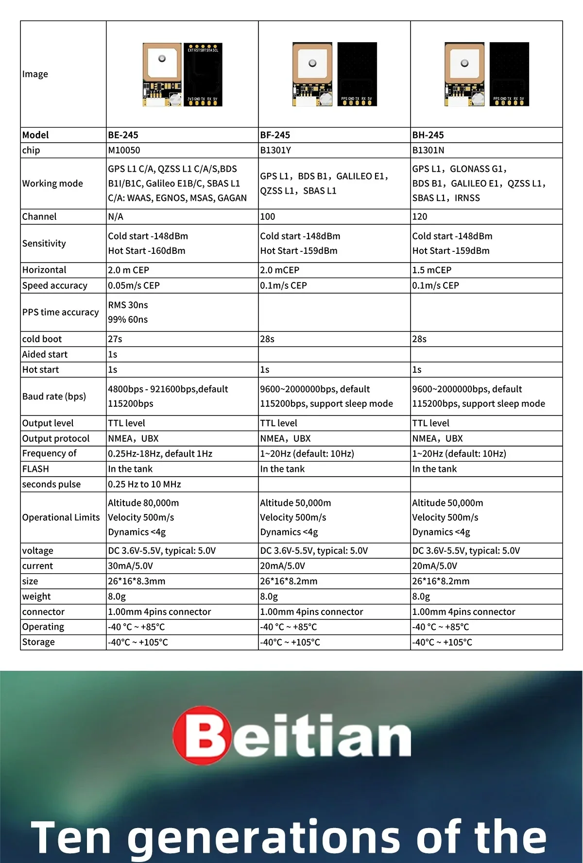
型號比較 (來自提供的表格)
| 項目 | BE-245 | BF-245 | BH-245 |
|---|---|---|---|
| 晶片 | M10050 | B1301Y | B1301N |
| 工作模式 | GPS L1 C/A, QZSS L1 C/A/S, BDS B1I/B1C, Galileo E1B/C, SBAS L1 C/A: WAAS, EGNOS, MSAS, GAGAN | GPS L1, BDS B1, GALILEO E1, QZSS L1, SBAS L1 | GPS L1, GLONASS G1, BDS B1, GALILEO E1, QZSS L1, SBAS L1, IRNSS |
| 頻道 | 不適用 | 100 | 120 |
| 靈敏度 | 冷啟動 -148dBm; 熱啟動 -160dBm | 冷啟動 -148dBm; 熱啟動 -159dBm | 冷啟動 -148dBm; 熱啟動 -159dBm |
| 水平定位精度 | 2.0 m CEP | 2.0 m CEP | 1.5 m CEP |
| 速度精度 | 0.05m/s CEP | 0.1m/s CEP | 0.1m/s CEP |
| PPS 時間精度 | RMS 30ns; 99% 60ns | ||
| 冷啟動 | 27秒 | 28秒 | 28秒 |
| 輔助啟動 | 1秒 | 1秒 | 1秒 |
| 熱啟動 | 1秒 | 1秒 | 1秒 |
| 波特率 (bps) | 4800bps - 921600bps,默認 115200bps | 9600-2000000bps,默認 115200bps,支持睡眠模式 | 9600-2000000bps,默認 115200bps,支持睡眠模式 |
| 輸出電平 | TTL 電平 | TTL 電平 | TTL 電平 |
| 輸出協議 | NMEA, UBX | NMEA, UBX | NMEA, UBX |
| 頻率 | 0.25Hz-18Hz,默認 1Hz | 1~20Hz(默認:10Hz) | 1~20Hz(默認:10Hz) |
| 操作限制 | 高度 80,000m;速度 500m/s;動態 <4g | 高度 50,000m;速度 500m/s;動態 <4g | 高度 50,000m;速度 500m/s;動態 <4g |
| 電壓 | 直流 3.6V-5.5v,典型:5.0V | 直流 3.6v-5.5v,典型:5.0V | 直流 3.6v-5.5v,典型:5.0V |
| 電流 | 30mA/5.0V | 20mA/5.0V | 20mA/5.0V |
| 尺寸 | 26*16*8.3mm | 26*16*8.2mm | 26*16*8.2mm |
| 重量 | 8.0g | 8.0g | 8.0g |
| 連接器 | 1.00mm 4針連接器 | 1.00mm 4針連接器 | 1.00mm 4針連接器 |
| 操作 | -40 ~ +85 | -40 ~ +85 | -40 ~ +85 |
| 儲存 | -40 ~ +105 | -40 ~ +105 | -40 ~ +105 |
詳細資訊
一個為固定翼和其他嵌入式導航設置而設計的緊湊型GNSS模組。

內建天線和小型佈局使得在狹小空間中的整合更為容易。
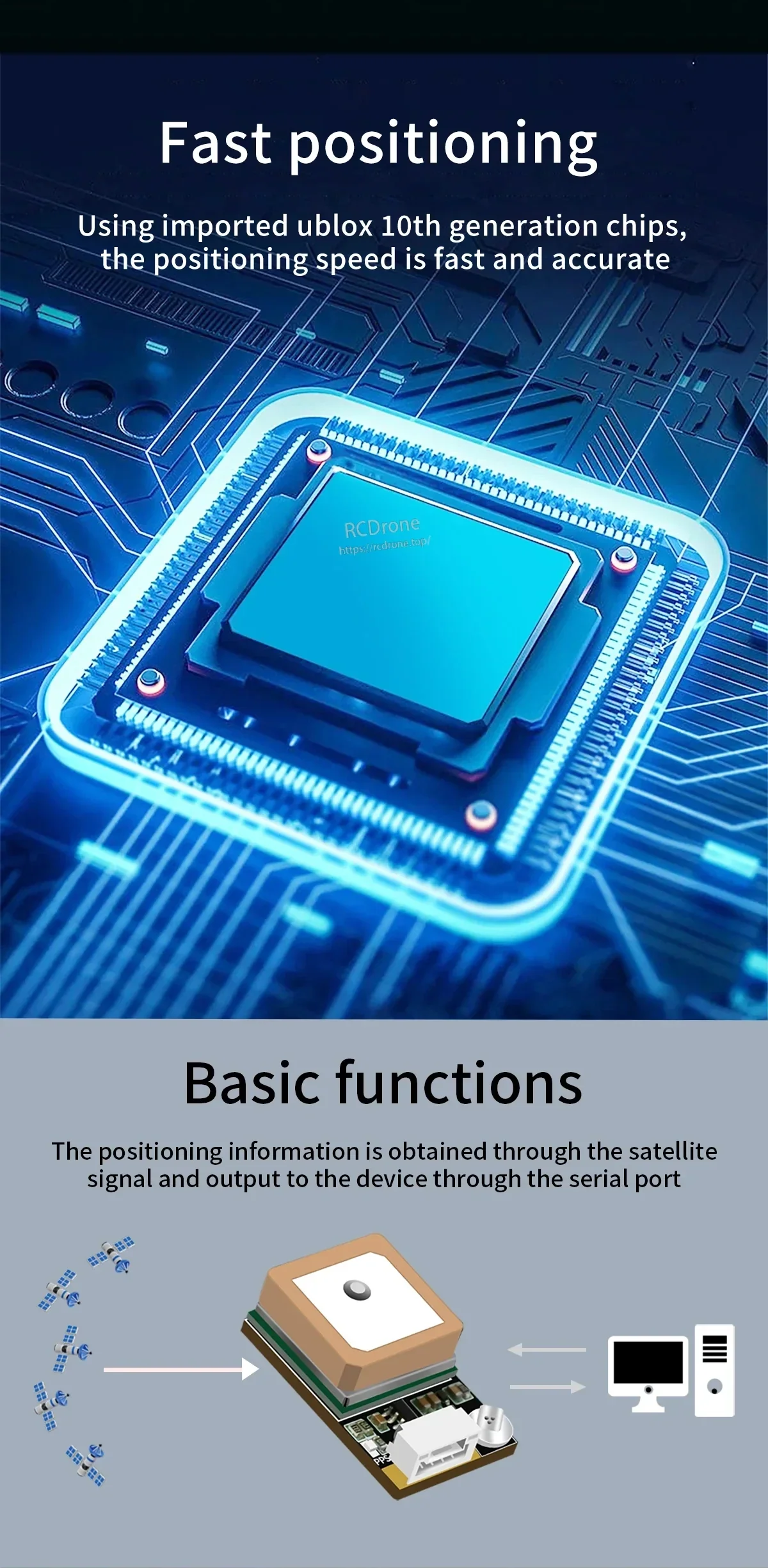
衛星數據通過TTL串行輸出提供,以便用於板載控制器。
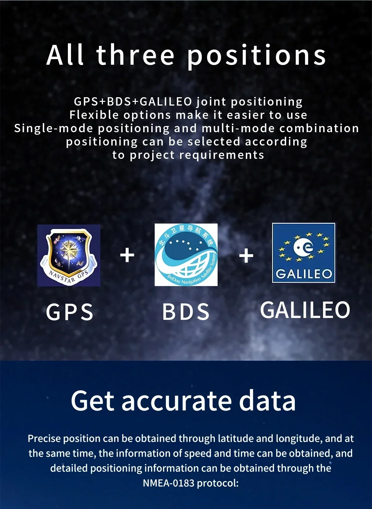
多種GNSS選項幫助將模組與不同的導航需求匹配。
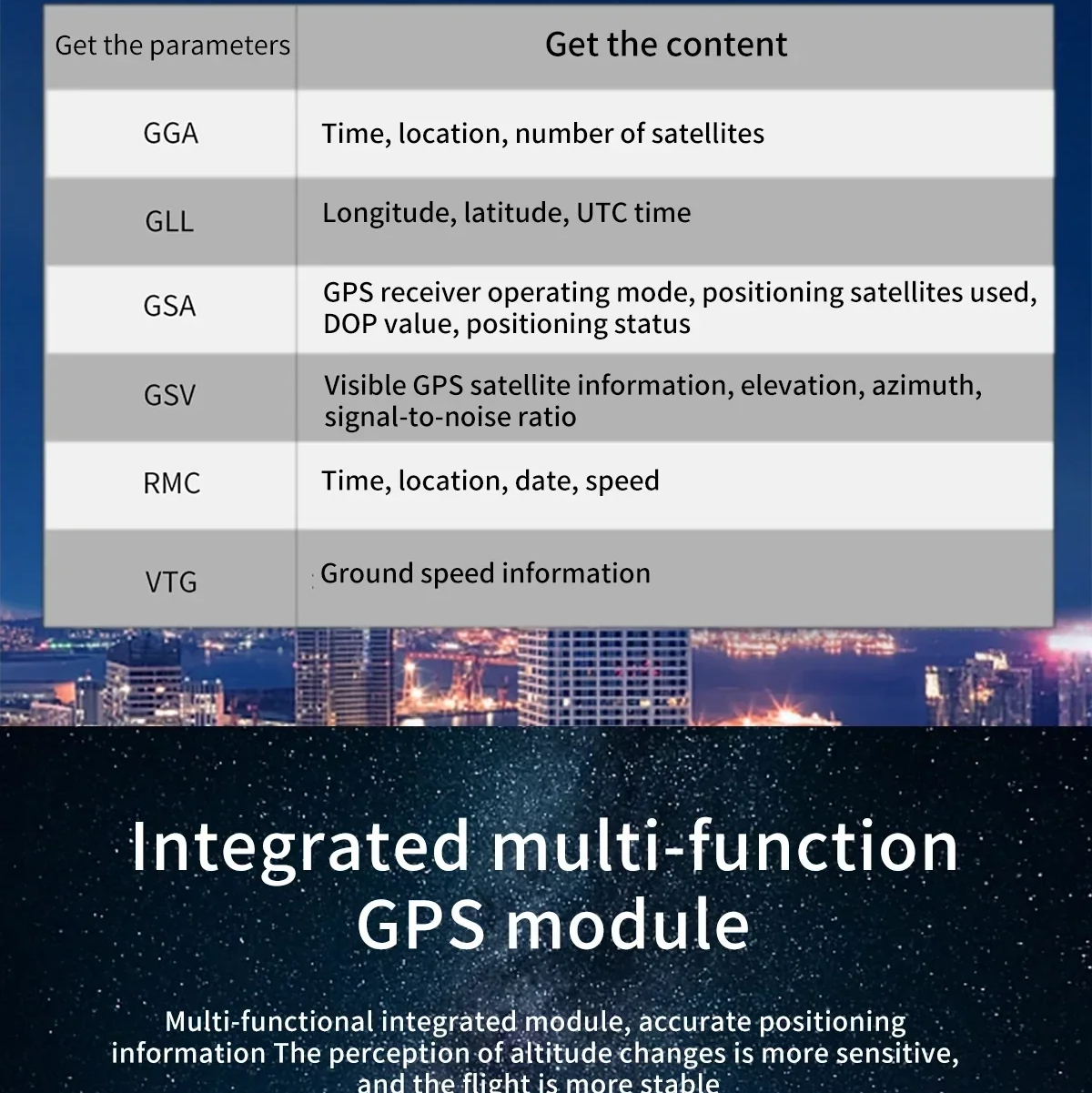
常見的NMEA語句提供位置、時間、衛星和速度數據。
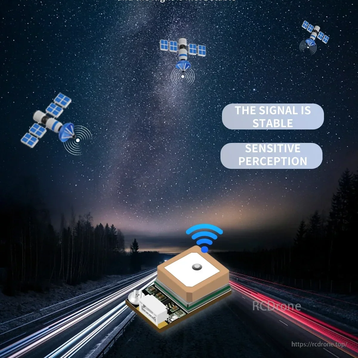
穩定的接收支持在嵌入式和移動應用中的一致定位。
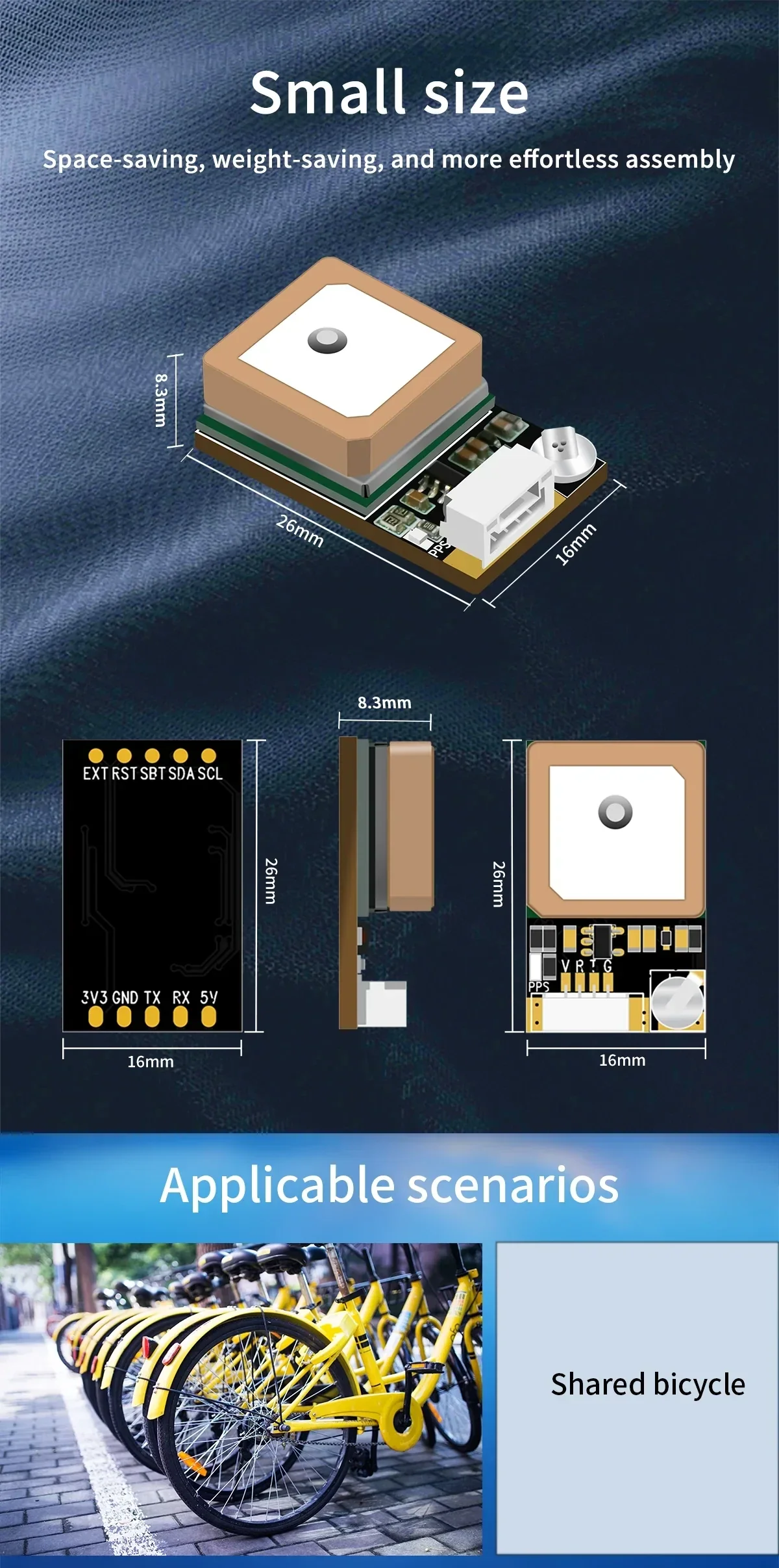
小型電路板尺寸有助於在輕量級構建中節省空間。
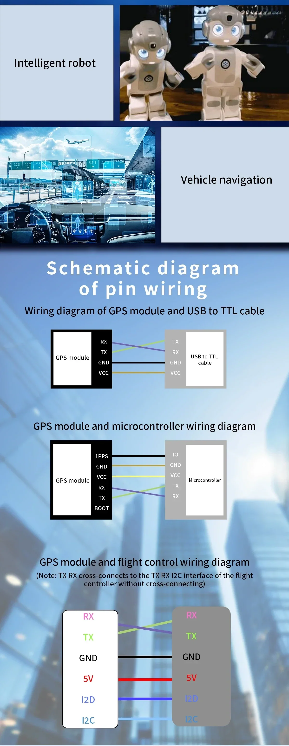
接線圖顯示模組如何連接到常見的TTL和控制介面。
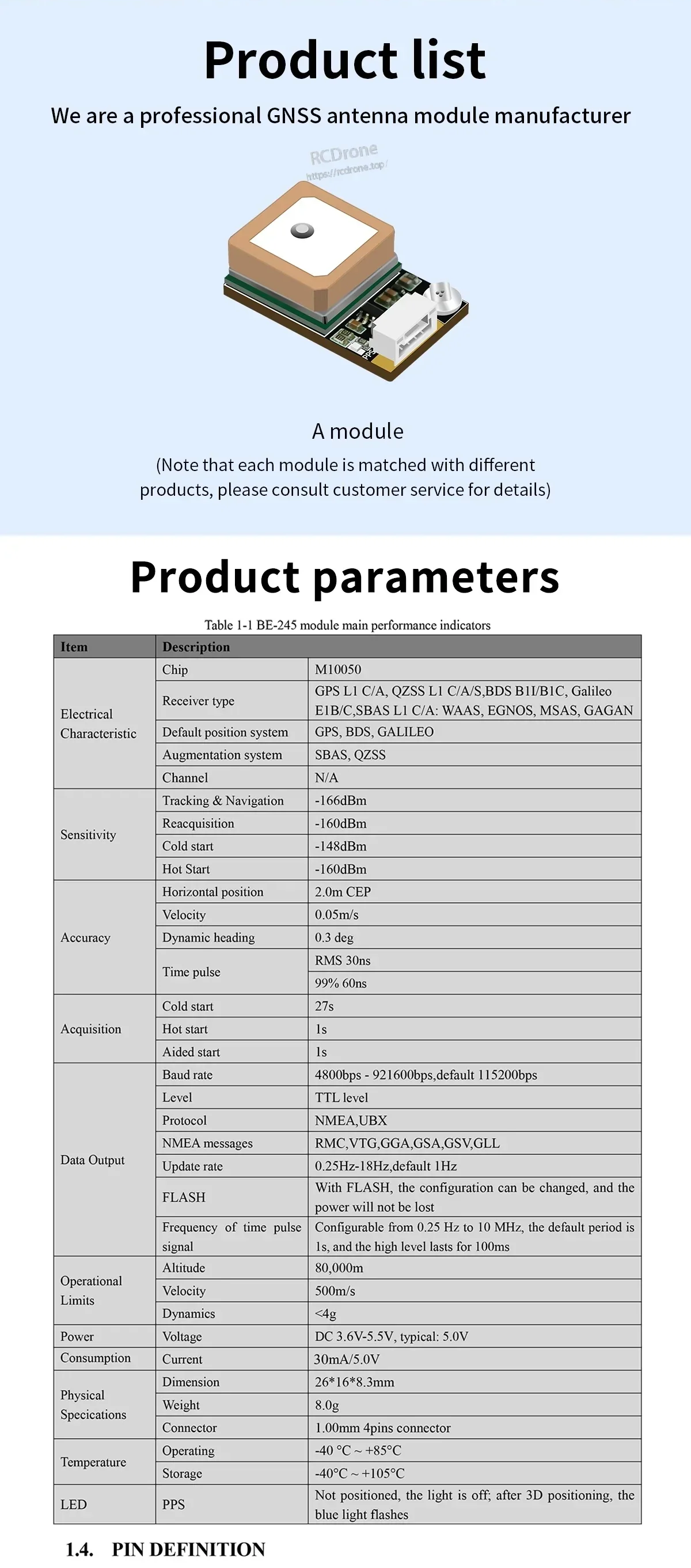
規格和引腳詳細信息一起列出,以便快速集成參考。
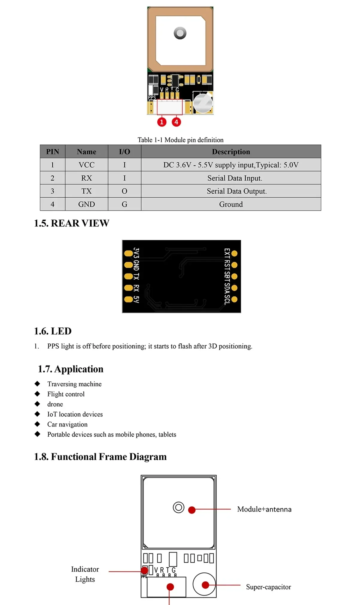
引腳標籤和電路板佈局有助於在安裝前確認方向。
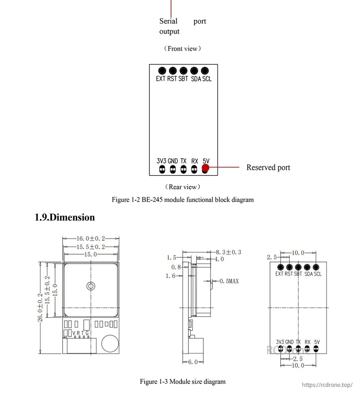
功能和尺寸圖紙支持外殼規劃和連接器放置。