CHIHAI 5–28V BLDC Speed Controller, 0–5V Analog & Dual PWM Outputs
CHIHAI 5–28V BLDC Speed Controller, 0–5V Analog & Dual PWM Outputs
CHIHAI MOTOR
無法載入取貨情況


Overview
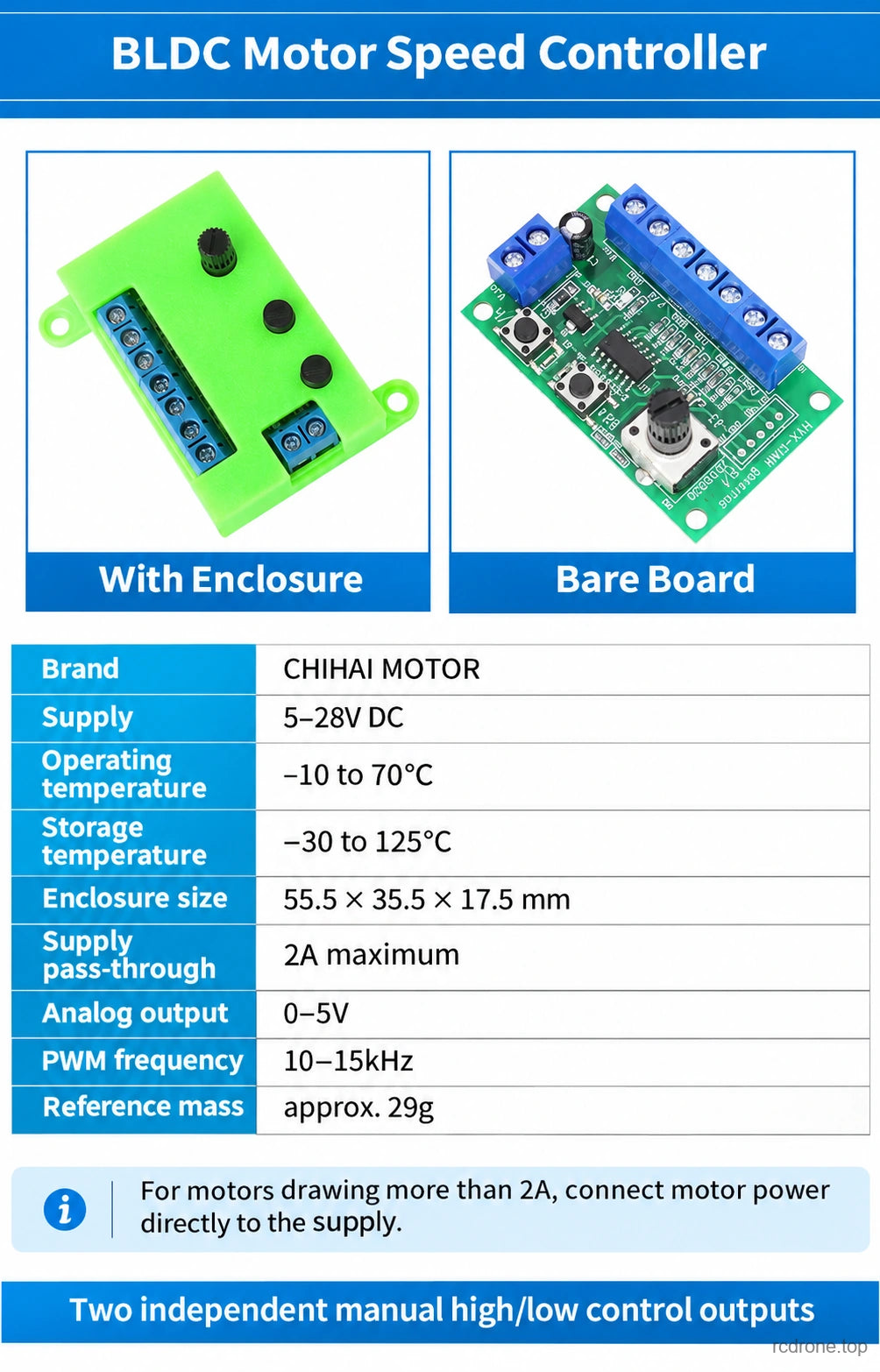
The CHIHAI MOTOR 5–28V PWM and analog motor controller provides manual speed adjustment for compatible brushless DC motors with a built-in driver or a separate driver that accepts its control signals. A rotary knob adjusts a 0–5V analog output and complementary PWM outputs, while separate buttons control direction and brake signals. Choose a bare board or a board with a green enclosure.
Features
- 0–5V analog speed output for compatible analog-controlled motor drivers.
- Non-inverted and inverted PWM speed outputs at 10–15kHz.
- Independent direction and brake control outputs, each switching between 5V and 0V.
- Screw-terminal connections and a rotary speed-control knob.
- Bare-board and enclosed versions with the same control functions.
Specifications
| Parameter | Value |
|---|---|
| Supply voltage | 5–28V DC; match the motor and driver requirements |
| Analog speed output | 0–5V |
| PWM output frequency | 10–15kHz |
| Direction and brake signal levels | 5V high / 0V low; both default high at power-on |
| Current through supply pass-through terminals | 2A maximum |
| Operating temperature | −10 to 70°C |
| Storage temperature | −30 to 125°C |
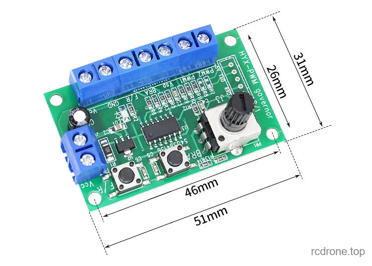
| Bare board outline | 51 × 31 mm |
| Bare board mounting-hole spacing | 46 × 26 mm |
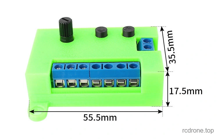
| Enclosure dimensions | 55.5 × 35.5 × 17.5 mm |
| Reference mass | Approximately 29g; configuration-specific mass is not specified |
Connections and Operation
This board generates speed, direction and brake control signals. It does not provide three-phase commutation for an undriven brushless motor. Confirm that the motor or its driver accepts the selected signal type and voltage levels before connecting it.
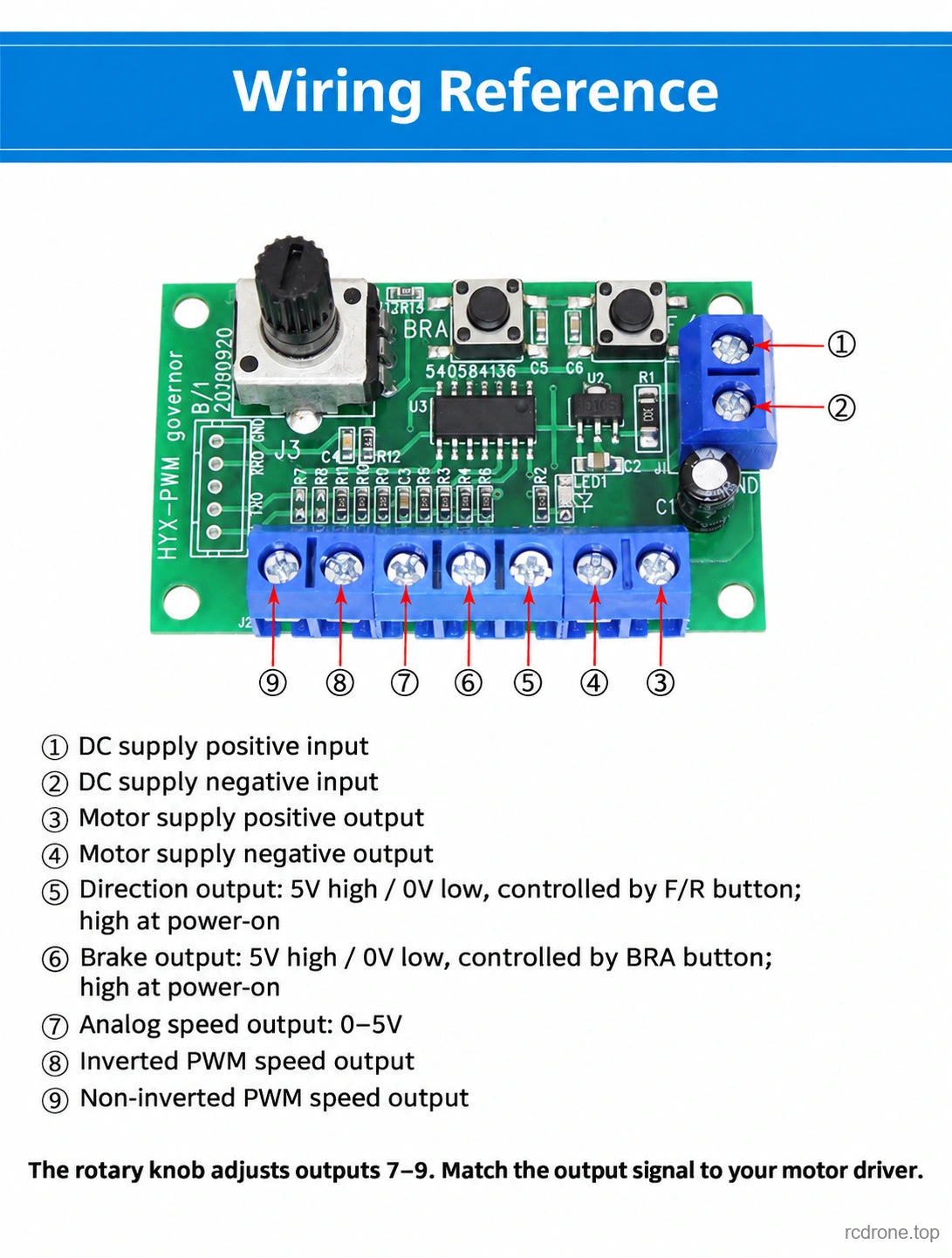
| Terminal | Function |
|---|---|
| 1 | DC supply positive input |
| 2 | DC supply negative input |
| 3 | Motor supply positive output |
| 4 | Motor supply negative output |
| 5 | Direction control output: 5V / 0V, switched by the F/R button; defaults high |
| 6 | Brake control output: 5V / 0V, switched by the BRA button; defaults high |
| 7 | 0–5V analog speed output |
| 8 | Inverted PWM speed output |
| 9 | Non-inverted PWM speed output |
The rotary knob adjusts outputs 7–9. The PWM outputs are complementary; use the polarity required by your motor driver. Direction and brake behavior depends on the connected motor driver.
Do not route more than 2A through the controller's supply pass-through. For a motor drawing more than 2A, power the motor directly from a suitable supply and follow its driver's control-ground requirements. Disconnect power before wiring, verify polarity and supply limits, and stop the motor before changing direction.
Applications
Manual bench adjustment of compatible BLDC motor systems, small mechanisms and motion-control projects that use a 0–5V or PWM speed command with separate direction and brake inputs.
What's Included
- Bare Board: one controller board.
- With Enclosure: one controller board fitted with a green enclosure.
Motor, motor driver, power supply and external wiring are not included.
FAQ
Can this board drive a three-wire brushless motor directly?
No. It supplies control signals for a compatible motor with an integrated driver or a separate compatible motor driver.
Which speed output should I use?
Choose terminal 7 for a 0–5V analog input, terminal 9 for non-inverted PWM, or terminal 8 for inverted PWM, according to the motor driver's requirements.
Can I use it with a motor that draws more than 2A?
The control signals may be used with a compatible driver, but motor power must bypass this board's 2A supply pass-through. Confirm signal compatibility and the driver's connection requirements.
Visual Details