CHIHAI CHR-GM37-BLDC3650 Brushless DC Gear Motor with Built-in Driver
CHIHAI CHR-GM37-BLDC3650 Brushless DC Gear Motor with Built-in Driver
CHIHAI MOTOR
تعذر تحميل مدى توفر الطلب


Overview
The CHIHAI MOTOR CHR-GM37-BLDC3650 is a 37 mm brushless DC gear motor with a built-in commutation driver,all-metal reduction gears,ball-bearing support and a6 mm D-shaft. Select the dedicated12V or24V motor,ratio and motor-only,bracket or external brushless speed-controller package.
Features
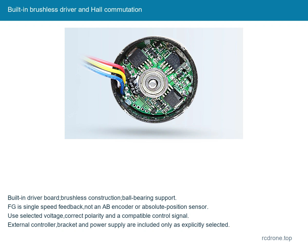
- Brushless permanent-magnet motor with integrated Hall commutation/driver board.
- Metal spur gearbox and ball-bearing construction.
- 0–5V speed command and separate CW/CCW direction input.
- FG speed-feedback output for compatible external counting.
- Optional mounting bracket and external speed-control module.
Specifications
| Item | Specification |
|---|---|
| Model | CHR-GM37-BLDC3650 |
| Design | Permanent-magnet brushless DC motor with all-metal spur reduction and built-in Hall commutation/driver board |
| Selectable supply | Dedicated12V or24V winding; not interchangeable |
| Gearbox diameter | 37 mm |
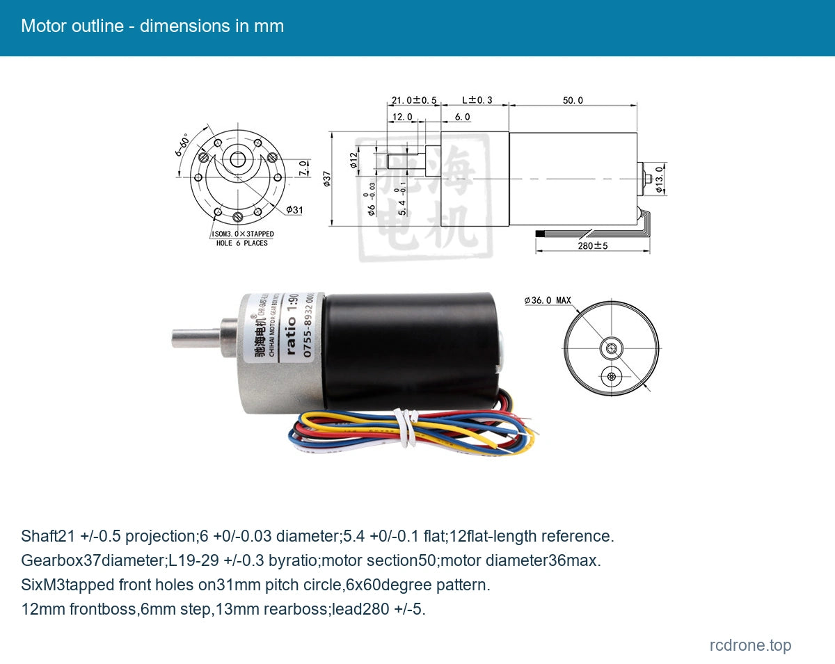
| Motor section | 50 mm length;36 mm maximum diameter reference |
| Output shaft | 6 mm diameter+0/-0.03,D-flat5.4+0/-0.1;21 ±0.5 mm projection;12 mm flat-length reference |
| Mounting | Six M3 tapped holes on31 mm pitch circle;6x60° pattern |
| Other outline references | 12 mm front boss;6 mm front step;13 mm rear boss;lead280 ±5 mm |
| Gearbox L | 19–29 mm,tolerance±0.3 mm,depends on ratio |
| Net mass | Approximately280 g,varies with reduction ratio |
| Speed command | Blue wire:0–5V PWM input;1.2–3.3V analog speed reference |
| FG feedback | Yellow wire open-collector output;6 pulses/revolution reference;external counting/ratio interpretation required |
| FG electrical reference | 5V/10kΩ pull-up;VOH minimum4V,VOL0–0.6V;output current maximum5mA |
| Direction command | White wire0–5V;high≥2V CCW,low≤0.2V CW in terminal table |
| Protection-current reference | 3A shutdown/protection reference in both voltage tables |
| External controller option | Brushless speed-control module in selected packages;motor already contains commutation driver |
Wiring and Speed Control
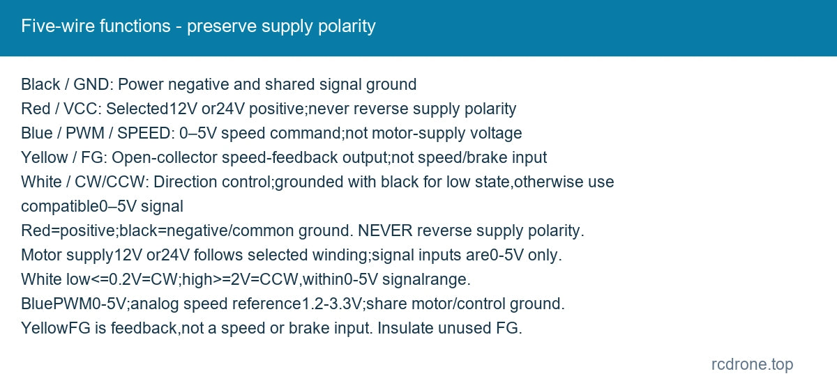
| Wire | Signal | Function |
|---|---|---|
| Black | GND | Power negative and shared signal ground |
| Red | VCC | Selected12V or24V positive;never reverse supply polarity |
| Blue | PWM / SPEED | 0–5V speed command;not motor-supply voltage |
| Yellow | FG | Open-collector speed-feedback output;not speed/brake input |
| White | CW/CCW | Direction control;grounded with black for low state,otherwise use compatible0–5V signal |
Red is supply positive and black is negative. Never reverse supply polarity to change direction; reversal is controlled by the white CW/CCW wire.12V and24V are separate motor selections,not a universal input range. The12V terminal table gives12V ±10% for the12V version; it must not be applied to the24V winding.
Blue accepts a0–5V PWM speed command; an analog1.2–3.3V speed reference is also listed. Use the compatible control signal and share black ground with motor-power negative. Keep the control source positive supply separate from motorVCC when providing a regulated control supply. Do not connect motorVCC to PWM,FG or direction signals. Where a potentiometer-style module is used,the blue command connects to its signal/wiper terminal and its control supply must remain within the allowed signal range.
FG is an open-collector speed-feedback output,with a5V/10kΩ pull-up reference,minimum4V high,0–0.6V low and maximum5mA output current. The count reference is6 pulses per revolution; account for motor versus gearbox shaft and actual reduction when interpreting measured speed. Do not mistake FG for an AB quadrature encoder or absolute position feedback.
Controller and Stop-Wiring Reference
The optional module is for brushless motor speed control; the motor already has a built-in commutation board. The alternate stop/braking wiring illustration is a separate mode without speed adjustment. Do not assume simultaneous speed control and braking,an emergency-stop rating or a dedicated brake lead from the five-wire motor. Keep the yellowFG lead insulated when not connected to a compatible feedback input; do not connect it to a speed or brake terminal. A6–30V DC input label in the external-controller illustration describes that module,not universal motor voltage,and is not an AC mains input.
Ratio and Gearbox Length
| Ratio reference | Gearbox L mm |
|---|---|
| 6.3:1 | 19 |
| 10:1 | 19 |
| 18.8:1 | 21.5 |
| 30:1 | 21.5 |
| 50:1 | 24 |
| 90:1 | 24 |
| 150:1 | 26.5 |
| 260:1 | 26.5 |
| 450:1 | 29 |
| 650:1 | 29 |
| 810:1 | 29 |
810:1 is a family-table reference only,not a selectable ratio here. Only actual in-stock combinations are offered;the motor-only650:1/24V combination is unavailable in this selection.
Motor Performance
No-load and rated values describe separate operating points. Maximum power is a reference,not continuous output at every ratio. Red torque cells state a maximum permitted load of35kgf·cm (3.5N·m rounded reference),not a separately specified rated torque. Exceeding it can damage the gears. The3A shutdown/protection reference is separate from rated current and is not a continuous operating target.
24V
Maximum power reference30W;no-load current≤320mA;shutdown/protection-current reference3A.
| Ratio | No-load rpm | Rated kgf·cm | Rated rpm | Rated A max |
|---|---|---|---|---|
| 6.3:1 | 1300 | 1.5 | 1070 | 1.1 |
| 10:1 | 830 | 2.5 | 670 | 1.1 |
| 18.8:1 | 425 | 4.5 | 355 | 1.1 |
| 30:1 | 270 | 7 | 225 | 1.1 |
| 50:1 | 165 | 12 | 135 | 1.1 |
| 90:1 | 90 | 22 | 75 | 1.1 |
| 150:1 | 55 | 35 maximum permitted load; rated value unspecified | 45 | 1.1 |
| 260:1 | 30 | 35 maximum permitted load; rated value unspecified | 27.5 | 0.6 |
| 450:1 | 18 | 35 maximum permitted load; rated value unspecified | 17 | 0.5 |
| 650:1 | 12.5 | 35 maximum permitted load; rated value unspecified | 12 | 0.4 |
| 810:1 | 10.2 | 35 maximum permitted load; rated value unspecified | 9.8 | 0.4 |
12V
Maximum power reference7W;no-load current≤200mA;shutdown/protection-current reference3A.
| Ratio | No-load rpm | Rated kgf·cm | Rated rpm | Rated A max |
|---|---|---|---|---|
| 6.3:1 | 650 | 0.8 | 530 | 0.85 |
| 10:1 | 415 | 1.2 | 335 | 0.85 |
| 18.8:1 | 215 | 2.2 | 178 | 0.85 |
| 30:1 | 135 | 3.5 | 112 | 0.85 |
| 50:1 | 82 | 6 | 67.5 | 0.85 |
| 90:1 | 45 | 11 | 37 | 0.85 |
| 150:1 | 27 | 18 | 23 | 0.85 |
| 260:1 | 15 | 32 | 13 | 0.85 |
| 450:1 | 9 | 35 maximum permitted load; rated value unspecified | 7.5 | 0.85 |
| 650:1 | 6.3 | 35 maximum permitted load; rated value unspecified | 5.5 | 0.85 |
| 810:1 | 5.2 | 35 maximum permitted load; rated value unspecified | 4.5 | 0.85 |
Installation
Match the6 mm shaft and21 mm projection to the mechanism,and use the six-M3 front mounting pattern. Confirm actual gear ratio,gearbox length and rear-lead clearance before fabrication. Avoid overload,prolonged stall,forcing the output shaft and shorting signal wires to motor power. Size the power supply and wiring for the selected voltage and load.
Applications
Suitable for compatible robot mechanisms,automation fixtures,small powered doors,positioning and pan assemblies using the selected reduction and external control signals. FG supplies speed feedback for a suitable controller;it is not a complete position-control system.
What's Included
One selected CHR-GM37-BLDC3650 motor with its five-wire lead. The bracket package adds the illustrated mounting bracket;the controller package adds the illustrated brushless speed-control module;the combined package includes both. A power supply,feedback counter,application controller and complete mechanism are not included.
FAQ
Does the bare motor need an external commutation driver?
It includes a built-in Hall commutation/driver board. An external compatible control signal or the selected speed-controller module provides speed/direction control as required.
Can I reverse the motor by swapping power polarity?
No. Keep red positive and black negative;use the white direction-control lead. Reversed supply can damage the built-in board.
Is the12V motor also suitable for24V?
No.12V and24V are distinct motor choices and must use their matching supply.
Is FG an AB encoder?
No. It is a single open-collector speed-feedback output with a6-pulse-per-revolution reference.
Visual Details