CNJCPTECH FD Series Three-Axis Force Sensors & FD18 Six-Axis Force/Torque Sensor
CNJCPTECH FD Series Three-Axis Force Sensors & FD18 Six-Axis Force/Torque Sensor
CNJCPTECH
تعذر تحميل مدى توفر الطلب


Overview
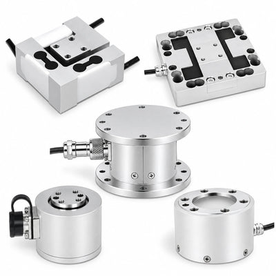
CNJCPTECH FD-series force sensors provide multi-directional load feedback for robotics, testing and industrial measurement. FD01-2, FD03, FD10-3 and FD13-1-2 measure three forces along X, Y and Z; FD18 measures six axes, combining Fx, Fy and Fz with Tx, Ty and Tz torque. Choose the model, load range and mounting geometry that match your equipment rather than treating every selection as the same sensor.
Features
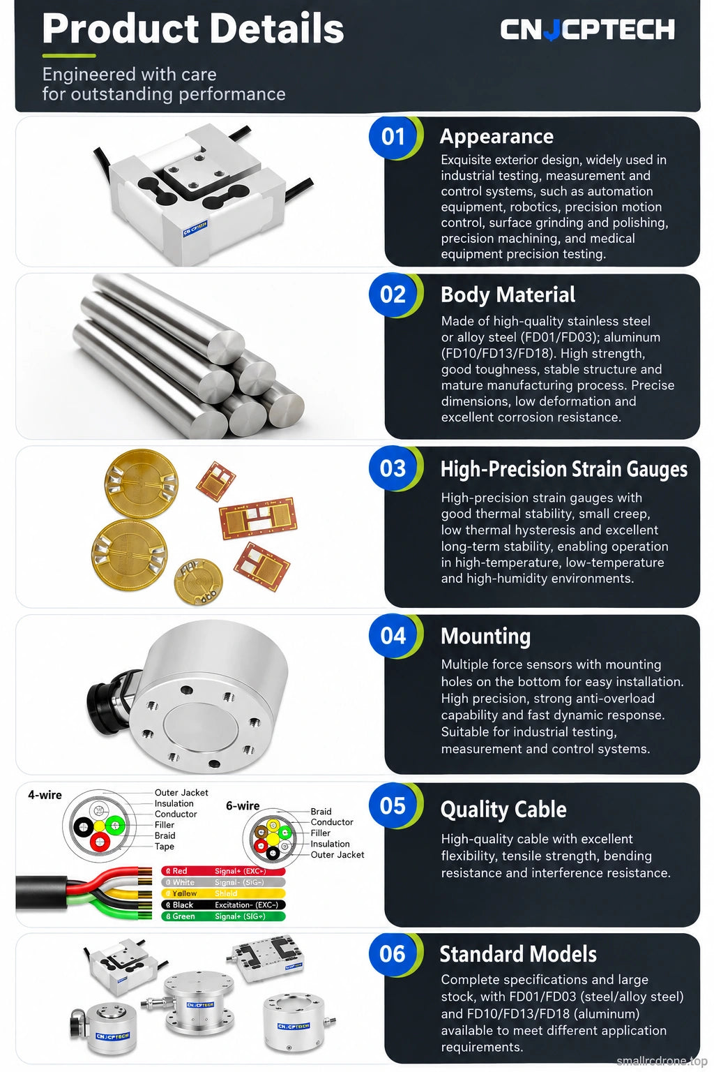
- Three-axis force models in cylindrical, flanged and compact block housings.
- FD18 six-axis force/torque selections for combined force and moment measurement.
- Model-specific ranges from 5 N low-force blocks to 5000 N planar sensors.
- Bridge-signal output for integration with compatible excitation and signal conditioning.
- IP66 protection for the listed three-force models; IP65 for FD18.
- Mechanical drawings and load-direction diagrams for fixture planning.
Configuration Guide
| Model | Axes | Offered ranges | Housing / geometry |
|---|---|---|---|
| FD01-2 | X, Y, Z forces | 50, 100, 200 N per axis | Steel cylindrical body, Ø46 mm reference |
| FD03 | X, Y, Z forces | 200, 500, 1000 N per axis | Steel flanged body, Ø96 mm flange reference |
| FD10-3 | X, Y, Z forces | 5, 10, 20, 50 N per axis | Aluminum 40 × 40 × 20 mm block |
| FD13-1-2 | X, Y, Z forces | 1000, 2000, 5000 N per axis | Aluminum planar body, 120 × 120 mm reference footprint |
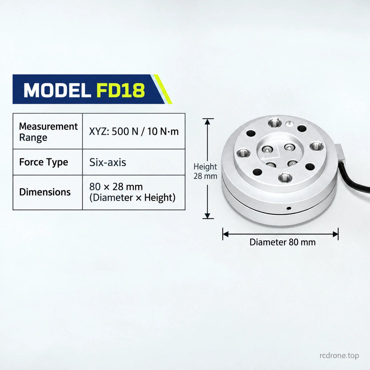
| FD18 | Fx, Fy, Fz + Tx, Ty, Tz | 50 N / 2 N·m; 200 N / 5 N·m; 500 N / 10 N·m | Aluminum circular body, Ø80 × 28 mm overall reference |
Three-axis selections measure forces, not three additional torque channels. Only the FD18 selections provide six-axis force/torque measurement. Range values identify the selected channel capacities; account for simultaneous loading and fixture moments when sizing a measurement system.
Specifications
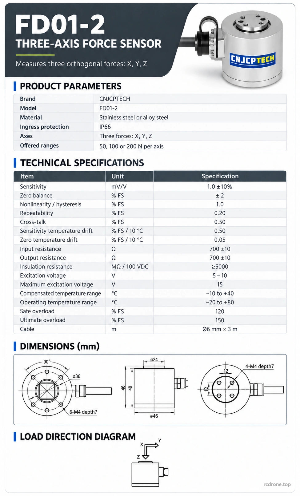
FD01-2
| Axes | Three forces: X, Y, Z |
|---|---|
| Offered ranges | 50, 100 or 200 N per axis |
| Material | Stainless steel or alloy steel |
| Ingress protection | IP66 |
| Sensitivity | 1.0 mV/V ±10% |
| Zero balance | ±2% FS |
| Nonlinearity / hysteresis | 1.0% FS each |
| Repeatability | 0.20% FS |
| Cross-talk | 0.50% FS |
| Sensitivity / zero temperature drift | 0.50 / 0.05% FS per 10 °C |
| Input / output resistance | 700 ±10 Ω each |
| Insulation resistance | ≥5000 MΩ at 100 VDC |
| Excitation / maximum | 5–10 V / 15 V |
| Compensated / operating temperature | −10 to +40 °C / −20 to +80 °C |
| Safe / ultimate overload | 120 / 150% FS |
| Cable | Ø6 mm × 3 m |
| Drawing size | Ø46 mm body; option image identifies 49 mm overall height; drawing has 40 / 46 mm section callouts. Use exact drawing for mounting |
FD03
| Axes | Three forces: X, Y, Z |
|---|---|
| Offered ranges | 200, 500 or 1000 N per axis |
| Material | Stainless steel or alloy steel |
| Ingress protection | IP66 |
| Sensitivity | 1.0 mV/V ±10% |
| Zero balance | ±2% FS |
| Nonlinearity | ≤0.1% FS |
| Hysteresis | ≤0.2% FS |
| Repeatability | ≤0.1% FS |
| Sensitivity / zero temperature drift | 0.1% FS per 10 °C each |
| Input / output resistance | 350 Ω or 700 Ω configuration, ±10 Ω |
| Insulation resistance | ≥5000 MΩ at 100 VDC |
| Excitation / maximum | 5–12 V / 15 V |
| Compensated / operating temperature | −10 to +60 °C / −20 to +80 °C |
| Safe / ultimate overload | 120 / 150% FS |
| Drawing size | Ø96 mm flanges; 65 mm overall height; Ø66 mm central body |
FD10-3
| Axes | Three forces: X, Y, Z |
|---|---|
| Offered ranges | 5, 10, 20 or 50 N per axis |
| Material | Aluminum alloy |
| Ingress protection | IP66 |
| Sensitivity | 1 mV/V |
| Zero output | 0.05 mV/V |
| Cross-talk | X→Y 0.5%; Y→X 0.5%; Z→X/Y 1%; X/Y→Z 1% FS |
| Hysteresis / repeatability | ≤0.1% FS each |
| Sensitivity / zero temperature drift | 0.05% FS/K each |
| Input / output resistance | 350 ±5 Ω each |
| Insulation resistance | 5 GΩ |
| Excitation / maximum | 2.5–5 V / 10 V |
| Compensated / operating temperature | −20 to +60 °C / −20 to +70 °C |
| Safe / ultimate overload | 150 / 150% FS |
| Drawing size | 40 × 40 × 20 mm overall; 18 mm body callout; 4 × M3 through mounting holes |
FD13-1-2
| Axes | Three forces: X, Y, Z |
|---|---|
| Offered ranges | 1000, 2000 or 5000 N per axis |
| Material | Aluminum alloy |
| Ingress protection | IP66 |
| Sensitivity | 0.5 mV/V |
| Zero output | 0.05 mV/V |
| Cross-talk | 1% FS |
| Hysteresis / repeatability | ≤0.1% FS each |
| Sensitivity / zero temperature drift | 0.01 / 0.02% FS/K |
| Input / output resistance | 780 / 700 Ω |
| Insulation resistance | 5 GΩ |
| Excitation / maximum | 1–10 V / 10 V |
| Compensated / operating temperature | −10 to +70 °C / −10 to +85 °C |
| Safe / ultimate overload | 150 / 150% FS |
| Drawing footprint | 120 × 120 mm; use the drawing for hole patterns and thickness details |
FD18
| Axes | Six: Fx, Fy, Fz and Tx, Ty, Tz |
|---|---|
| Offered force / torque pairs | 50 N / 2 N·m; 200 N / 5 N·m; 500 N / 10 N·m |
| Material | Aluminum alloy |
| Ingress protection | IP65 |
| Nonlinearity | 0.2% FS |
| Accuracy | 0.3% FS |
| Coupling accuracy | 1.5% FS |
| Repeatability | 0.2% FS |
| Resolution | 0.1% FS |
| Zero drift | 0.1% FS / 30 min |
| Zero temperature drift | 0.2% FS / 10 °C |
| Input / output resistance | 350 Ω each |
| Output | mV bridge signal |
| Excitation | 5–15 VDC |
| Storage / operating temperature | −20 to +75 °C / 0 to +40 °C |
| Operating humidity | 20–80% RH |
| Ultimate overload | 300% FS |
| Drawing dimensions | Ø80 mm overall diameter and 28 mm height; Ø63 mm section and Ø50 / Ø31.5 H7 locating references |
FS means full scale. Values apply to the named model, not to the entire family. Safe and ultimate overload ratings are limits rather than normal working loads. Match excitation, calibration sensitivity, conditioning and controller input to the selected sensor.
Signal Conditioning and Installation
The bridge wiring reference identifies red EXC+, black EXC−, green SIG+ and white SIG−, with a separate shield. Multi-axis installations require the appropriate channel wiring and conditioning arrangement for the selected model; verify its connector pinout before applying power. FD18 provides mV bridge signals, rather than an integrated RS485 interface.
Analog amplifiers, transmitters, multichannel acquisition units and displays shown in the conditioning diagram are separately configured equipment. Their analog-voltage, current, serial or network output choices do not establish built-in output interfaces on every sensor. Align the load surface and X/Y/Z directions with the test fixture, secure the base through the designated mounting holes, and avoid unintended side loads or cable tension. Use each model's drawing for exact hole patterns, threads and locating tolerances.
Applications
- Robot end-effectors and contact-force feedback with suitable mechanical adapters.
- Multi-directional force measurement in laboratory and industrial test fixtures.
- Assembly, pushing, pulling and contact-load monitoring within the selected range.
- Low-force testing with FD10-3 or higher-load fixtures with FD13-1-2.
- Combined force and torque research using FD18.
What's Included
- 1 × CNJCPTECH sensor in the selected model and range, with its fitted cable/connection arrangement.
External signal conditioners, displays, acquisition systems, robot arms, fixtures and mounting adapters are not included. Family and conditioning illustrations help identify compatible system components; they do not constitute a bundled package.
Visual Details