CHIHAI CHR-GM25-BLDC2430 Brushless DC Gear Motor, 12V or 24V
CHIHAI CHR-GM25-BLDC2430 Brushless DC Gear Motor, 12V or 24V
CHIHAI MOTOR
Impossible de charger la disponibilité du ramassage


Overview
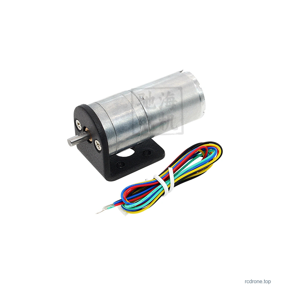
The CHIHAI MOTOR CHR-GM25-BLDC2430 is a25 mm brushless DC gear motor with metal reduction gears, an internal Hall drive board and five power/control leads. Choose the12V or24V motor, reduction ratio and motor-only, bracket or BLDC speed-controller package.
Features
- Brushless motor with copper winding and onboard Hall commutation electronics.
- Metal gear reduction with a4 mm D-shaped output shaft.
- PWM speed command, direction command and separate FG pulse output.
- Four packages with optional mounting bracket and speed-control board.
Specifications
| Item | Specification |
|---|---|
| Model | CHR-GM25-BLDC2430 / GM25-BL2430 |
| Motor | Brushless DC gear motor with internal Hall drive electronics |
| Selected operating voltage | 12V or24V DC; match the selected motor |
| Nominal power reference | Approximately6 W; operating values depend on voltage, ratio and load |
| Gearbox diameter | 25 mm |
| Motor body | 24.4 mm diameter;30.8 mm can-length drawing reference |
| Output shaft | 4 mm D-shaft;12 +/-0.5 mm projection;8 mm flat length |
| Shaft fitting drawing | 4 mm diameter+0/-0.03 mm;3.5 mm flat dimension+0/-0.1 mm |
| Front mount | Two M3 tapped holes,17 mm spacing reference |
| Gearbox length L | 19-27 mm by ratio; tolerance+/-0.3 mm |
| Mass reference | Approximately95 g; varies by configuration |
| Cable | Five-wire power and control lead set |
| Control | PWM speed input, CW/CCW direction input and FG Hall pulse output |
Gear Ratio and Length
| Reference ratio | Gearbox L (mm) |
|---|---|
| 4.4:1 | 19 |
| 9.3:1 | 19 |
| 20:1 | 19 |
| 34:1 | 21 |
| 45:1 | 21 |
| 75:1 | 23 |
| 100:1 | 23 |
| 125:1 | 25 |
| 217:1 | 25 |
| 362:1 | 27 |
| 478:1 | 27 |
The362:1 column is a family reference and is not a selectable combination here. Body length varies with reduction ratio; shaft projection is separate from gearbox length.
Electrical and Torque Performance
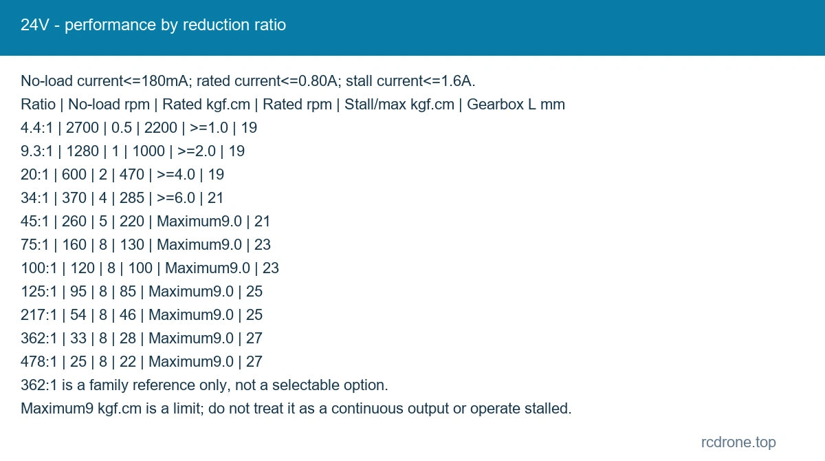
Values apply to the stated voltage and reduction ratio. No-load, rated and stall conditions are distinct. Do not operate stalled or treat the maximum9 kgf·cm limit as a continuous torque rating.
12V
No-load current ≤130 mA; rated current ≤0.50 A; stall current ≤1.3 A.
| Ratio | No-load rpm | Rated torque kgf·cm | Rated rpm | Stall / maximum torque kgf·cm |
|---|---|---|---|---|
| 4.4:1 | 1350 | 0.3 | 1100 | >=0.5 |
| 9.3:1 | 640 | 0.6 | 500 | >=1.0 |
| 20:1 | 300 | 1.2 | 235 | >=2.0 |
| 34:1 | 185 | 2 | 143 | >=3.0 |
| 45:1 | 130 | 2.5 | 110 | >=4.5 |
| 75:1 | 80 | 4.5 | 64 | >=7.0 |
| 100:1 | 60 | 6 | 49 | Maximum9.0 |
| 125:1 | 48 | 7.5 | 39 | Maximum9.0 |
| 217:1 | 27 | 8 | 22 | Maximum9.0 |
| 362:1 | 16.5 | 8 | 13 | Maximum9.0 |
| 478:1 | 12.5 | 8 | 10 | Maximum9.0 |
24V
No-load current ≤180 mA; rated current ≤0.80 A; stall current ≤1.6 A.
| Ratio | No-load rpm | Rated torque kgf·cm | Rated rpm | Stall / maximum torque kgf·cm |
|---|---|---|---|---|
| 4.4:1 | 2700 | 0.5 | 2200 | >=1.0 |
| 9.3:1 | 1280 | 1 | 1000 | >=2.0 |
| 20:1 | 600 | 2 | 470 | >=4.0 |
| 34:1 | 370 | 4 | 285 | >=6.0 |
| 45:1 | 260 | 5 | 220 | Maximum9.0 |
| 75:1 | 160 | 8 | 130 | Maximum9.0 |
| 100:1 | 120 | 8 | 100 | Maximum9.0 |
| 125:1 | 95 | 8 | 85 | Maximum9.0 |
| 217:1 | 54 | 8 | 46 | Maximum9.0 |
| 362:1 | 33 | 8 | 28 | Maximum9.0 |
| 478:1 | 25 | 8 | 22 | Maximum9.0 |
Power, Direction and PWM Wiring
| Wire | Signal | Electrical function |
|---|---|---|
| Red | Vm / VCC+ | Motor power at selected12V or24V DC; not a5V logic supply |
| Black | GND | Power/control ground |
| Yellow | CW/CCW | 0-5V direction input; highCCW, lowCW; high threshold2.0V min, low0.5V max |
| Green | FG | Hall pulse output;6pulses/cycle reference; high6V max, low0.5V max, signal-current reference2mA |
| Blue | PWM | 0-5V active-low control; typical15-25kHz, maximum60kHz; high or openOFF, lowON; thresholds2.0V min/0.5V max |
Keep motor supply voltage away from the0-5V PWM and direction inputs. Observe power polarity; reverse supply can damage the internal electronics. The motor contains its commutation drive, so its five wires are not three raw motor-phase leads. FG is a pulse output for a compatible external measurement circuit; it is not an absolute position encoder or a promise of closed-loop operation.
Optional BLDC Speed Controller
The illustrated board power range is6-30V DC; use the motor-selected12V or24V supply. It must not be connected directly to household AC mains. In the speed-control configuration, connect as follows:
| Board connection | Wiring |
|---|---|
| Board V+ / V- | Appropriate DC power supply positive / negative |
| Motor VCC+ | Motor red wire |
| Motor GND- | Motor black wire |
| CW/CCW | Motor yellow direction wire |
| PWM | Motor blue control wire |
| BRAKE | Leave unconnected in speed-control wiring |
| FG green | Leave unconnected to this speed-controller board; it does not measure FG speed |
The supplied controller does not read the motor FG signal. Leave the green wire isolated from the board and leave BRAKE unconnected in this configuration. Do not assume an emergency-stop or braking function is provided by this motor-and-board combination. Board switches can control speed/direction only where the connected motor supports the corresponding input.
Bracket and Packages
| Package | Included |
|---|---|
| Motor Only | One selected motor and five-wire lead set |
| Motor + Bracket | One motor, lead set and mounting bracket |
| Motor + BLDC Speed Controller | One motor, lead set and BLDC speed controller |
| Motor + Bracket + BLDC Controller | One motor, lead set, mounting bracket and BLDC speed controller |
The bracket drawing includes a26.5 mm motor opening,33 mm upright reference,26.5 mm base reference and3 mm material thickness. Confirm all mounting dimensions against the drawing before fabrication. Couplings, wheels, power supply and a complete mechanism are not included.
Applications
Use the selected motor for robot mechanisms, electronic locks, automatic rotary equipment and small positioning platforms with suitable external controls. Match voltage, load and operating speed; avoid overload and prolonged stall.
What's Included
One selected motor with its power/control leads. A bracket and BLDC speed controller are included only when named in the package. The controller package does not include a power supply or FG speed-measurement module.
FAQ
Does the motor need an external three-phase driver?
Its Hall commutation drive is built in. Use the documented DC power and logic/control inputs; the optional board provides a convenient speed-control interface.
Does the optional board measure FG speed?
No. Keep the green FG lead isolated from this board, or connect it only to a suitable separate measurement circuit.
Can the blue control lead use12V?
No. Blue PWM and yellow direction inputs are0-5V logic inputs, separate from12V/24V motor power.
Visual Details