


CHIHAI MOTOR CHW-GW12T-15BY Geared Stepper Motor
CHIHAI MOTOR CHW-GW12T-15BY Geared Stepper Motor
CHIHAI MOTOR
Impossible de charger la disponibilité du ramassage


Overview
The CHIHAI MOTOR GW12T-15BY is a compact geared stepper with a metal worm-reduction stage,3 mm D-shaft and integral four-wire lead assembly. Choose one of six nominal ratios and a motor-only,button-driver,enclosed-driver or flange-coupler package. The603:1 selection is the steel-plate version. This compact electric motor requires sequenced bipolar stepper excitation.
Features
- 18° input motor step with ratio-dependent output increments.
- Metal gear train and compact worm-reduction layout.
- 3 mm shaft with 2.5 mm D-flat and 8 mm projection reference.
- Separate standard and 603 steel-plate dimensions.
- Optional button-operated driver,enclosed driver or flange coupler.
Specifications
| Specification | Value / scope |
|---|---|
| Family | CHIHAI MOTOR GW12T-15BY geared two-phase stepper |
| Construction | Metal reduction gears with worm stage and integral lead assembly |
| Selected nominal ratios | 42:1,118:1,236:1,302:1,603:1 steel-plate version,1030:1 |
| Input motor step | 18° per step |
| Output shaft | 3 mm D-shaft;2.5 mm flat,standard tolerance +0/−0.1 mm;8.0±0.3 mm projection;7.5 mm flat-length reference |
| Shaft diameter tolerance | 3 mm(+0/−0.03) drawing reference |
| Standard assembly drawing | 28.7 mm body length;12 mm frame width;18 mm frame height;10 mm frame-depth reference;15 mm motor diameter |
| Standard front interfaces | Two1.4 mm front holes;8.50 mm spacing;4 mm vertical reference;4 mm shaft register;0.7 mm shoulder |
| Standard rear/motor references | 1.8/4.0 mm offsets;10.7 mm motor height;5 mm rear register;1 mm rear projection |
| 603 steel-plate drawing | 2.5 mm shaft-flat tolerance +0/−0.05 mm;29.8±0.3 mm assembly length;12 mm width(+0/−0.1);18 mm height(+0/−0.1);10±0.1 mm frame-depth reference |
| 603 steel-plate mounting | Three1.4 mm hole references;8.5/11/2.5(+0/−0.05) mm hole-pattern references;0.6 mm shoulder |
| Standard motor weight | Approximately18 g with integral lead assembly;no separately evidenced603 steel-plate weight |
| Lead/connector | 165±10 mm;UL1571AWG30 drawing reference;1.25 mm four-position connector,51021-0400 housing reference |
| Electrical input-motor test | 5V DC with 6219 driver reference;160 mA per phase |
| Phase resistance/inductance | 30 Ω±7% per phase;9.5 mH per phase |
| Excitation | Two phases,two-phase-on,bipolar drive |
| Input-motor torque references | Pull-out>4 gf·cm at 500pps;holding>16 gf·cm at 0pps;these are before gearbox reduction |
| Pulse references | Response>1200pps;self-starting>900pps |
| Coil insulation/tests | Class E coils;100VAC for 1 second dielectric test;50 MΩ at 500VDC insulation resistance |
| Operating temperature | 0–55°C reference |
| Gearbox performance test scope | 5V6219 reference,150 mA/phase separately listed;5–12V drive guide |
| Lead-marking scope | 105° wire-marking reference does not establish complete-motor operating temperature |
Ratio Selection and Output References
The following table is the gearbox-output reference under the illustrated5V/6219 test conditions. The150mA phase-current reference in this table and 160mA input-motor electrical reference are separately stated test values. Holding torque is referenced to0pps,pull-out torque to500pps,and speed to1000pps.
| Selected nominal ratio | Precise ratio | Output step(°) | Speed at 1000pps(rpm) | Holding torque(kgf·cm) | Pull-out torque(kgf·cm) | Output direction | Frame reference |
|---|---|---|---|---|---|---|---|
| 42:1 | 42.00:1 | 0.429 | 71 | 0.25 | 0.12 | Same as input | Standard reference |
| 118:1 | 118.07:1 | 0.1528 | 25 | 0.5 | 0.3 | Same as input | Standard reference |
| 236:1 | 236.13:1 | 0.0762 | 12.7 | 1.0 | 0.7 | Same as input | Standard reference |
| 302:1 | 301.73:1 | 0.0597 | 10 | 1.4 | 0.9 | Same as input | Standard reference |
| 603:1 | 603.45:1 | 0.0298 | 5 | Maximum3.0 | 1.8 | Same as input | Steel-plate version |
| 1030:1 | 1030.40:1 | 0.0177 | 2.9 | Maximum3.0 | 3.0 | Opposite input | Standard reference |
The3.0 kgf·cm holding values for 603:1 and 1030:1 are maximum permissible limits,not minimum torque guarantees. Input-motor torque values in gf·cm must not be confused with gearbox-output values in kgf·cm. Output-step figures are nominal reference values and do not establish positioning accuracy.
Additional Ratio Family References
Only the six ratios in the selected table are offered here. The following broader family chart is retained for mechanical reference and does not add other selectable configurations.
| Family nominal ratio | Precise ratio | Output relative to input motor |
|---|---|---|
| 21:1 | 21.00:1 | Same as input |
| 42:1 | 42.00:1 | Same as input |
| 79:1 | 78.71:1 | Same as input |
| 118:1 | 118.07:1 | Same as input |
| 236:1 | 236.13:1 | Same as input |
| 302:1 | 301.73:1 | Same as input |
| 390:1 | 389.62:1 | Same as input |
| 520:1 | 519.49:1 | Same as input |
| 603:1 | 603.45:1 | Same as input |
| 700:1 | 700.98:1 | Same as input |
| 780:1 | 779.24:1 | Same as input |
| 1030:1 | 1030.40:1 | Opposite input |
Version Fit and Wiring
Standard package photographs are shared references. The603:1 option is specifically the steel-plate version and uses the separate29.8 mm drawing;standard drawings show28.7 mm. Keep the corresponding frame,mounting holes and shoulder references separate when checking fit.
Connector pin order is 1 brown A−,2 black A+,3 white B− and 4 red B+. Brown/black form phase A;white/red form phase B. The excitation sequence below is viewed from the flange side,as in the wiring diagram. For the 1030:1 version,the gearbox output rotates opposite the input motor;the other listed ratios rotate in the same relative direction.
| Pin | Wire color | Phase |
|---|---|---|
| 1 | Brown | A− |
| 2 | Black | A+ |
| 3 | White | B− |
| 4 | Red | B+ |
| Coil | Step1 | Step2 | Step3 | Step4 |
|---|---|---|---|---|
| Brown A− | — | ON | ON | — |
| Black A+ | ON | — | — | ON |
| White B− | — | — | ON | ON |
| Red B+ | ON | ON | — | — |
Driver and Thermal References
The following is a separate voltage/current drive guide for the 30Ω winding. It is not a statement that every board and current setting is interchangeable. The motor requires sequenced excitation from a compatible driver.
| Test voltage | Recommended drive rate(pps) | Suggested drive current(A) |
|---|---|---|
| 12.0V | 1000 | ≤0.25 |
| 7.40V | 1000 | ≤0.15 |
| 6.00V | 1000 | ≤0.10 |
| 5.00V | 1000 | ≤0.08 |
| 3.70V | 700 | ≤0.07 |
Applied voltage = back EMF + winding current×resistance. During extended operation,monitor temperature and use cooling pauses or auxiliary cooling when needed. Avoid stalled or overloaded operation.
The selected button-driver and enclosed-driver packages contain the pictured board versions. Check their actual interface,supply and current settings. A separate earlier test-driver illustration shows inward jumper6–18V and outward jumper4–6V,with 6–12V recommended;those jumper instructions apply only to that illustrated earlier board. They must not be transferred to the selected button/enclosed boards.
Applications
Compatible small robots,adjustable furniture,miniature follow-focus mechanisms,pan-tilt units and automatic photography mechanisms where the selected ratio,load,driver and mounting fit. Worm gearing can resist back-driving,but holding behavior depends on the actual ratio and load.
What's Included
| Selected package | Contents |
|---|---|
| Motor Only | 1 motor with integral lead/connector assembly |
| Motor + Button Driver | 1 motor and 1 pictured button-operated driver |
| Motor + Enclosed Button Driver | 1 motor and 1 pictured enclosed button-operated driver |
| Motor + Flange Coupler | 1 motor and 1 flange-coupler assembly |
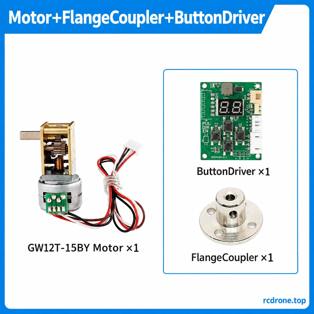
| Motor + Flange Coupler + Button Driver | 1 motor,1 flange coupler and 1 button-operated driver |
The actual frame follows the selected ratio:603:1 is the steel-plate version. A power supply,host controller and application equipment are not included. Motor-only selections do not include a driver or coupler.
FAQ
Which option uses the steel-plate frame?
The603:1 selection. Its separate drawing shows a 29.8 mm assembly-length reference,while standard drawings show28.7 mm.
Does the 1030:1 output turn in the same direction as the input motor?
No. It turns opposite the input motor. The other listed ratio references show the same relative direction.
Is3.0 kgf·cm a minimum holding-torque guarantee?
No. For603:1 and 1030:1,it is a maximum permissible holding limit.
Can the four leads be connected directly to DC power?
Use a compatible two-phase bipolar stepper driver and the indicated phase pairs. Sequenced excitation controls rotation.
Do the older test-board jumper ranges apply to the included boards?
No. Match the actual selected button or enclosed board's ratings and interface.
Visual Details


