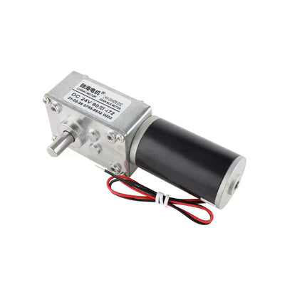
CHIHAI CHR-GM37-520 ABHL DC Gear Motor with 11 PPR Hall Encoder
CHIHAI CHR-GM37-520 ABHL DC Gear Motor with 11 PPR Hall Encoder
CHIHAI MOTOR
Tidak dapat memuatkan ketersediaan pengambilan


Overview
The CHIHAI MOTOR CHR-GM37-520 ABHL is a 37 mm DC gear motor with an 11 PPR AB Hall encoder and a 6 mm D-shaped output shaft. Choose the connector and package, nominal motor voltage and gear ratio for robot drive mechanisms requiring speed or position feedback.
Features
- All-metal reduction gears and copper motor winding.
- Reversible brushed DC drive with separate AB encoder signals.
- PH2.0, XH2.54 and covered XH2.54 encoder configurations.
- Motor-only, mounting-bracket, 65 mm wheel and 80 mm wheel packages.
Specifications
| Item | Specification |
|---|---|
| Model | CHR-GM37-520 ABHL / JGB37-520 |
| Design | Brushed DC motor, metal reduction gears, copper winding, reversible rotation |
| Selectable motor supply | 6V, 12V or 24V DC; match the selected version |
| Gearbox diameter | 37 mm |
| Output shaft | 6 mm D-shaft; 21 ± 0.5 mm projection; 12 mm flat length; flat dimension 5.4 +0/-0.1 mm |
| Motor body reference | 32.8 mm diameter; 23 mm can length |
| Mounting | Six M3 tapped holes on 31 mm pitch circle; drawing includes 6-120° annotation; confirm hole orientation from drawing before machining |
| Net motor mass | Approximately 152 g; varies by ratio |
| Nominal ratio options | 6:1, 10:1, 18:1, 30:1, 50:1, 90:1, 150:1, 270:1, 450:1 |
| Encoder | AB incremental magnetic Hall, 11 PPR motor-shaft base resolution; 22 poles / 11 pole pairs |
| Encoder supply | Separate DC 3.3V or DC 5V |
| Output | AB square-wave signals, onboard pull-up/shaping resistors; response frequency100 kHz |
| Connections | PH2.0 six-pin, XH2.54 six-pin, or XH2.54 with encoder cover |
| Included cable | Matching six-wire connection lead set |
Ratio and Mechanical References
The selector names 6:1 and 18:1 correspond to the 6.3:1 and 18.8:1 reference columns. Ratios are nominal; the 18.8:1 column lists 207 output pulses/revolution, a rounded reference. Decoder counts depend on edge-counting method.
| Reference ratio | Gearbox length L (mm) | Output pulses/revolution |
|---|---|---|
| 6.3 | 19 | 69.3 |
| 10 | 19 | 110 |
| 18.8 | 21.5 | 207 |
| 30 | 21.5 | 330 |
| 50 | 24 | 550 |
| 90 | 24 | 990 |
| 150 | 26.5 | 1650 |
| 270 | 26.5 | 2970 |
| 450 | 29 | 4950 |
Electrical Performance
Values apply to the named voltage and ratio. Rated and stall torque are distinct; do not operate stalled. Torque is not a payload rating. The kgf·cm and N·m columns are independently rounded reference values, not exact conversions.
24V
Maximum output power reference 12.0 W; no-load current ≤100 mA; rated current ≤0.95 A; stall current ≤2.5 A.
| Ratio | No-load rpm | Rated kgf·cm | Rated N·m | Rated rpm | Stall kgf·cm |
|---|---|---|---|---|---|
| 6.3:1 | 1530 | 0.6 | 0.06 | 850 | 1.2 |
| 10:1 | 960 | 1 | 0.1 | 540 | 2 |
| 18.8:1 | 510 | 1.8 | 0.18 | 285 | 4 |
| 30:1 | 320 | 3 | 0.3 | 180 | 6 |
| 50:1 | 192 | 4.8 | 0.48 | 105 | 10 |
| 90:1 | 107 | 8.5 | 0.85 | 60 | 17 |
| 150:1 | 64 | 14.5 | 1.4 | 36 | 25 |
| 270:1 | 35 | 20 | 2 | 20 | 35 |
| 450:1 | 21 | 25 | 2.5 | 14 | 35 |
12V
Maximum output power reference 7.0 W; no-load current ≤160 mA; rated current ≤1.2 A; stall current ≤3.5 A.
| Ratio | No-load rpm | Rated kgf·cm | Rated N·m | Rated rpm | Stall kgf·cm |
|---|---|---|---|---|---|
| 6.3:1 | 1530 | 0.6 | 0.06 | 850 | 1.2 |
| 10:1 | 960 | 1 | 0.1 | 540 | 2 |
| 18.8:1 | 510 | 1.8 | 0.18 | 285 | 4 |
| 30:1 | 320 | 3 | 0.3 | 180 | 6 |
| 50:1 | 192 | 4.8 | 0.48 | 105 | 10 |
| 90:1 | 107 | 8.5 | 0.85 | 60 | 17 |
| 150:1 | 64 | 14.5 | 1.4 | 36 | 25 |
| 270:1 | 35 | 20 | 2 | 20 | 35 |
| 450:1 | 21 | 25 | 2.5 | 14 | 35 |
6V
Maximum output power reference 2.0 W; no-load current ≤100 mA; rated current ≤0.35 A; stall current ≤1.7 A.
| Ratio | No-load rpm | Rated kgf·cm | Rated N·m | Rated rpm | Stall kgf·cm |
|---|---|---|---|---|---|
| 6.3:1 | 760 | 0.2 | 0.02 | 570 | 0.7 |
| 10:1 | 480 | 0.3 | 0.03 | 360 | 1 |
| 18.8:1 | 205 | 0.6 | 0.06 | 192 | 1.9 |
| 30:1 | 160 | 1 | 0.1 | 120 | 3 |
| 50:1 | 95 | 3 | 0.3 | 72 | 5.5 |
| 90:1 | 53 | 4.8 | 0.48 | 40 | 9 |
| 150:1 | 32 | 8.6 | 0.86 | 24 | 16 |
| 270:1 | 18 | 14 | 1.4 | 13 | 30 |
| 450:1 | 10 | 20 | 2 | 8 | 35 |
Wiring and Encoder Feedback
Use PCB labels and the matching connector orientation. The diagram terminal order is M1, GND, C2, C1, VCC, M2. M1/M2 power the motor at its selected voltage; reverse their polarity to reverse rotation. GND is encoder ground, C2 is channel B, C1 is channel A, and VCC is the separate 3.3V/5V encoder supply. Do not connect 12V or 24V motor power to encoder VCC. Wire colors and connector orientation vary between PH and XH configurations; do not assume a shared color pinout.
The 11 PPR figure is motor-shaft base resolution. Output-shaft pulses equal the base resolution multiplied by actual gear ratio; quadrature edge counts depend on the external decoder. A suitable external motor driver and feedback controller are required for closed-loop operation.
Wheel and Bracket Packages
The bracket option adds one mounting bracket. Wheel kits include the selected motor, one wheel, bracket, coupling and shown installation hardware. The 65 mm wheel reference is 27 mm wide; the 80 mm reference is 35 mm wide. Wheel artwork shows alternate tread/color examples; these are not separate selectable options and no specific tread or rim color is guaranteed. The 80 mm assembly photograph includes a bracket, although its parts are shown separately in the 65 mm photograph.
Applications
- Self-balancing and differential-drive robot development using external control electronics.
- Inspection carts, line-following robots and compact mobile platforms.
- Camera positioning and powered lifting mechanisms within the selected motor ratings.
What's Included
One selected encoder gear motor and matching cable; add-on bracket or wheel-kit parts only as named in the selected package. A wheel kit is a single-motor kit, not a two-wheel robot set. Power supply, motor driver, encoder counter, controller and complete robot are not included.
Installation
Confirm the selected connector pin labels, shaft fit and mounting drawing before applying power or machining a mount. The covered motor has a different rear envelope. Avoid overload, sustained stall and forcing the output shaft.
FAQ
Is 11 PPR the resolution at the gearbox output?
No. It is the motor-shaft base resolution; multiply by the actual reduction ratio for output pulses, then account for the decoder counting method.
Can encoder VCC use the motor supply?
Only a regulated 3.3V or 5V encoder supply is specified. Keep it separate from the selected 6V, 12V or 24V motor circuit.
Does a wheel kit contain two motors?
No. Each selected package contains one motor and one wheel with the pictured matching mounting parts.
What changes with the connector option?
Choose PH2.0 six-pin, XH2.54 six-pin, or XH2.54 with a protective encoder cover. Match the cable and board labels for the version selected.
Visual Details