CHIHAI GM25-370 Hall Encoder DC Gear Motor and Wheel Kits, 6V/12V/24V
CHIHAI GM25-370 Hall Encoder DC Gear Motor and Wheel Kits, 6V/12V/24V
CHIHAI MOTOR
Tidak dapat memuatkan ketersediaan pengambilan


Overview
The CHIHAI MOTOR CHR-GM 25-370ABHL DC gear motor combines a 25 mm metal gearbox with 11PPR AB Hall feedback. Select the package, nominal motor voltage and exact speed/ratio configuration. Choose a bare encoder motor or a motor kit with one 65 mm wheel or one 60 mm Mecanum wheel.
Features
- Metal reduction gears and 4 mm D-shaped output shaft.
- AB quadrature magnetic feedback with matching cable.
- Distinct winding/speed choices, including different speeds at the same nominal reduction.
- Blue/red road tread, yellow basic, blue high-grip and Mecanum wheel packages.
Specifications
| Brand / model | CHIHAI MOTOR / CHR-GM 25-370ABHL |
| Motor | Brushed DC gear motor with metal reduction gears and AB magnetic Hall feedback |
| Selectable drive | 6 V, 12 V or 24 V winding; voltage, speed and ratio must match the selected configuration |
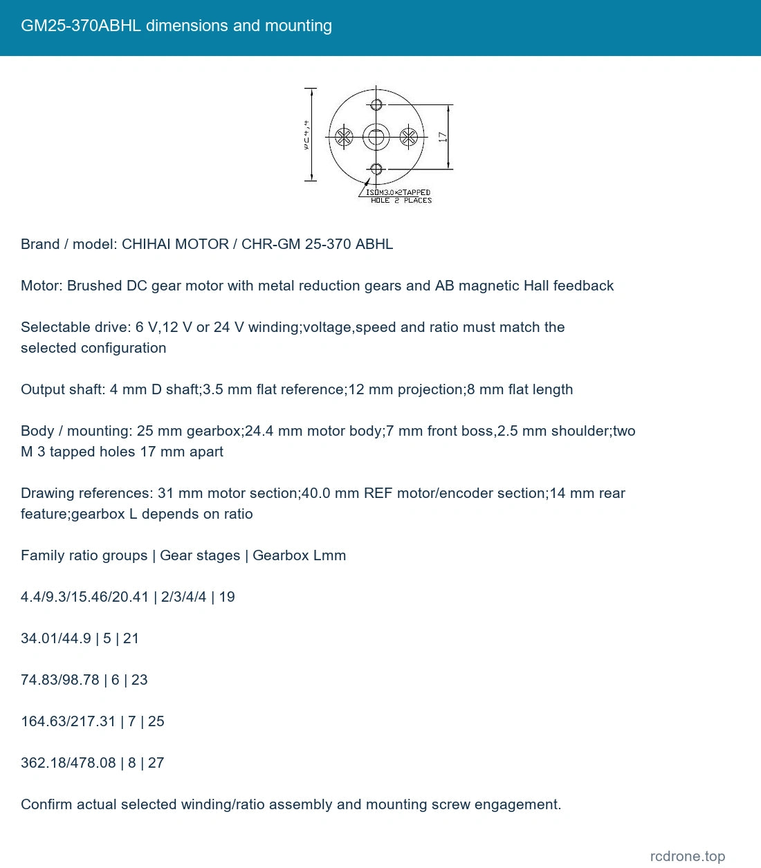
| Output shaft | 4 mm D shaft; 3.5 mm flat reference; 12 mm projection; 8 mm flat length |
| Body / mounting | 25 mm gearbox; 24.4 mm motor body; 7 mm front boss, 2.5 mm shoulder; two M 3 tapped holes 17 mm apart |
| Drawing references | 31 mm motor section; 40.0 mm REF motor/encoder section; 14 mm rear feature; gearbox L depends on ratio |
| Encoder | 11PPR at motor shaft, AB quadrature square wave; 22 magnetic poles/11pole pairs |
| Encoder supply / response | Separate 3.3 V or 5 V DC logic; 100kHz reference; onboard pull-up/shaping resistors |
| Connection | PH 2.0 six-position connection with matching lead; follow marked board orientation |
| Mass references | Approximately 100–200 g depending on ratio/package; shipping weight differs |
Voltage-Specific Performance
The following family operating columns distinguish no-load speed, rated speed and torque. Match voltage, ratio and no-load speed together; equal ratio labels do not identify the same winding. Nonselectable operating points remain family references rather than extra purchasable combinations.
6 V winding references
| Ratio : 1 | No-load rpm | No-load mA | Rated kgf.cm | Rated N.m | Rated rpm | Rated A | Stall A | Stall kgf.cm | Hall output reference | Gearbox Lmm |
|---|---|---|---|---|---|---|---|---|---|---|
| 10 | 600 | ≤60 | 0.9 | 0.09 | 310 | ≤0.8 | ≤2.7 | 1.8 | 102.3 | 19 |
| 20 | 300 | ≤100 | 1.8 | 0.177 | 160 | ≤0.8 | ≤2.7 | 3.6 | 224.5 | 19 |
| 34 | 210 | ≤130 | 5.2 | 0.5 | 110 | ≤1.1 | ≤3.5 | 10 | 341.2 | 21 |
| 34 | 175 | ≤130 | 2.9 | 0.28 | 90 | ≤1.1 | ≤3.0 | 6 | 341.2 | 21 |
| 75 | 100 | ≤130 | 7 | 0.69 | 55 | ≤1.5 | ≤3.5 | 10 | 823.1 | 23 |
12 V winding references
| Ratio : 1 | No-load rpm | No-load mA | Rated kgf.cm | Rated N.m | Rated rpm | Rated A | Stall A | Stall kgf.cm | Hall output reference | Gearbox Lmm |
|---|---|---|---|---|---|---|---|---|---|---|
| 4.4 | 2700 | ≤200 | 0.8 | 0.08 | 1600 | ≤1.5 | ≤5.6 | 1.8 | 44 | 19 |
| 10 | 1280 | ≤200 | 1.7 | 0.17 | 700 | ≤1.5 | ≤5.6 | 3.5 | 102.3 | 19 |
| 20 | 600 | ≤200 | 3.5 | 0.34 | 350 | ≤1.5 | ≤5.6 | 7 | 224.5 | 19 |
| 34 | 350 | ≤200 | 5.8 | 0.57 | 180 | ≤1.7 | ≤5.6 | 12 | 341.2 | 21 |
| 20 | 220 | ≤130 | 2.9 | 0.28 | 130 | ≤1.0 | ≤2.5 | 5 | 224.5 | 19 |
| 45 | 140 | ≤150 | 4.3 | 0.42 | 70 | ≤0.8 | ≤2.5 | 8.5 | 493.9 | 21 |
24 V winding references
| Ratio : 1 | No-load rpm | No-load mA | Rated kgf.cm | Rated N.m | Rated rpm | Rated A | Stall A | Stall kgf.cm | Hall output reference | Gearbox Lmm |
|---|---|---|---|---|---|---|---|---|---|---|
| 4.4 | 2700 | ≤150 | 0.6 | 0.059 | 1200 | ≤2.4 | ≤5.0 | 1 | 44 | 19 |
| 10 | 1280 | ≤150 | 1.4 | 0.14 | 580 | ≤2.4 | ≤5.0 | 2.2 | 102.3 | 19 |
| 20 | 600 | ≤150 | 2.8 | 0.27 | 300 | ≤2.4 | ≤5.0 | 4.5 | 224.5 | 19 |
| 34 | 350 | ≤150 | 5 | 0.49 | 170 | ≤2.4 | ≤5.0 | 8 | 341.2 | 21 |
| 45 | 265 | ≤150 | 6.5 | 0.64 | 130 | ≤2.4 | ≤5.0 | 10 | 493.9 | 21 |
| 24(ref; verify 180 rpm) | 180 | ≤100 | 3 | 0.29 | 110 | ≤1.3 | ≤2.5 | 6 | 341.2 | 21 |
The 24 V 180 rpm selection retains its 34: 1 label, but its operating reference column carries 24: 1. Confirm the actual assembly reduction before ratio-dependent design or output-count calculations. The voltage/speed choice is preserved; no corrected ratio is assumed. Stall values are not continuous ratings; avoid overload and stalled operation.
Hall output reference equals 11 base pulses per motor revolution multiplied by actual reduction; the nominal selector ratio and decoder counting convention may differ. Do not infer closed-loop positioning accuracy from pulse count alone.
Encoder and Motor Wiring
| Diagram order / marked signal | Function |
|---|---|
| M 1 | Motor terminal 1 |
| GND | Encoder logic ground |
| C 1 | Encoder A output |
| C 2 | Encoder B output |
| VCC | Encoder logic 3.3 V /5 V |
| M 2 | Motor terminal 2 |
Read the connector from the marked board viewing direction; do not infer wire colors from another model. Supply encoder VCC with 3.3 V or 5 V and retain correct GND polarity. Motor voltage belongs only on M 1/M 2. Reverse M 1/M 2 after stopping to reverse motor direction; do not reverse encoder logic power. A motor driver, MCU, feedback processor and power supply are separate.
Mechanical Fit and Accessories
| Precise family ratios : 1 | Gear-stage references | Gearbox Lmm |
|---|---|---|
| 4.4/9.3/15.46/20.41 | 2/3/4/4 | 19 |
| 34.01/44.9 | 5 | 21 |
| 74.83/98.78 | 6 | 23 |
| 164.63/217.31 | 7 | 25 |
| 362.18/478.08 | 8 | 27 |
Check the actual selected winding/ratio assembly, shaft fit, screw depth and rear encoder clearance. Family lengths above extend beyond the retail selections. The mounting bracket references 26.5 mm width, 33 mm height/foot length, 3 mm thickness, 8 mm front opening, two 3.2 mm front holes 17 mm apart, 10 mm foot opening andfour 3.4 mm foot holes on 16x 14 mm spacing. The hex coupling references 18 mm length, 12 mm across flats, 13.75 mm across corners, a 4 mm shaft bore and transverse M 4 clamping thread.
The four conventional wheel kits use 65 mm diameter x 27 mm width wheels. The Mecanum wheel is 60 mm diameter x 32 mm width. For an omnidirectional platform, coordinate a four-wheel set with appropriate left/right handedness; each listed Mecanum package contains only one wheel, and handedness is not a separate selector here.
What's Included
- Encoder Motor Only: one selected motor with Hall feedback and matching lead.
- Each 65 mm kit: one selected motor/lead, one selected wheel, one bracket, one hex coupling and pictured screws, set screws and hex key.
- 60 mm Mecanum kit: one selected motor/lead, one Mecanum wheel, bracket, coupling and pictured mounting hardware/hex key.
Package photos show alternative configurations, not a multi-motor bundle. A complete vehicle, chassis, driver, controller and power supply are not included.
Applications
Small robot drives, line-following and balancing-vehicle development, smart-home mechanisms, motorized fixtures and compact camera motion where the selected load, speed, shaft and feedback interface fit the design. Printer, cleaning-robot, lock and industrial-equipment examples illustrate possible applications; complete machines and software are not supplied.
Installation and Operation
Use the selected motor voltage; for example, a 12 V winding is not a 24 V winding. Verify wiring and mechanical clearance before operation, keep screws clear of gears, and avoid overload or prolonged stall. Gear noise and available torque vary with speed and load.
FAQ
Are two 34: 1 configurations at one voltage interchangeable?
No. Their winding and speed/load points can differ; match the exact selected no-load speed and the voltage-specific table.
Does the Mecanum kit include four wheels?
No. It includes one wheel and one motor. A complete omnidirectional wheel set requires coordinated left/right wheels.
Can the encoder run from the motor voltage?
No. Its logic supply is 3.3 V or 5 V, independent of the selected 6 V/12 V/24 V motor winding.
Visual Details