CHIHAI GW4632-BL2430 Brushless Worm DC Gear Motor, 12V/24V
CHIHAI GW4632-BL2430 Brushless Worm DC Gear Motor, 12V/24V
CHIHAI MOTOR
Não foi possível carregar a disponibilidade de retirada


Overview
The CHIHAI MOTOR CHW-GW 4632-BL 2430 is a brushless DC gear motor with built-in Hall commutation electronics and right-angle worm reduction. Choose the actual ratio, 12 V or 24 V winding, and motor-only, bracket or brushless speed-controller package.
Features
- Built-in driver allows DC-powered brushless operation without a separate three-phase ESC.
- Worm reduction, 6 mm D-shaft and threaded shaft center.
- Separate PWM, direction and FG pulse connections through a five-wire interface.
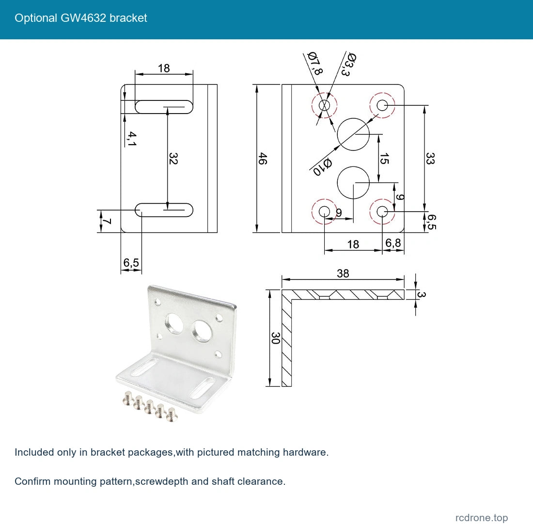
- Optional matching bracket and external speed-control board.
Specifications
| Brand / model | CHIHAI MOTOR / CHW-GW 4632-BL 2430 |
| Construction | Brushless DC motor with built-in Hall commutation driver and worm reduction |
| Winding supply | 12 V or 24 V DC as selected; controller 6–30 V input reference does not replace motor rating |
| Retail ratio labels | 32: 1, 65: 1, 158: 1, 200: 1, 337: 1, 564: 1, 1019: 1; first performance column uses 32.5: 1 actual reference |
| Output shaft | 6 mm D-shaft,+0/−0.03 diameter; 5.4 mm across flat,+0/−0.1 |
| Shaft / center thread | 18.5 mm projection, 12 mm flat reference; M 3×0.5 center thread, 12 mm effective depth |
| Gearbox references | 46×32 mm outline; 25.2 mm case thickness; 18 mm and 33 mm mounting references |
| Drawing features | Four M 3 mounting references; four 7.4 mm recess features; 24.4 mm motor diameter and 30.8 mm motor reference |
| Connector | A 1001WS, 1.0 mm pitch, five-pin interface |
| Reference net mass | Approximately 165 g; ratio-dependent and excluding accessories/packing |
| Protection reference | Motor power cuts off when load current exceeds 0.6 A per electrical table; do not rely on this as sole system protection |
| Feedback | FG Hall output 6 pulses per motor revolution; gearbox output reference 6×actual ratio |
| Mechanical holding | Worm resistance to back-driving depends on ratio/load; not a safety brake |
Winding Performance Reference
The selector uses the nominal 32: 1 label; its reference table and FG count use 32.5: 1. Other columns keep their stated ratios. Rated torque is kgf·cm. Maximum-power labels are reference headings rather than guaranteed mechanical power at every load point. Stall is not a continuous operating condition.
12 V
4 W maximum-power reference; no-load current≤140 mA. The electrical table gives a 0.6 A overload-cutoff reference.
| Reference ratio | No-load rpm | Rated kgf·cm | Rated rpm | Rated A | Output FG pulses |
|---|---|---|---|---|---|
| 32.5: 1 | 185 | 2 | 150 | ≤0.55 | 195 |
| 65: 1 | 92 | 4 | 75 | ≤0.55 | 390 |
| 158: 1 | 37 | 9 | 30 | ≤0.55 | 948 |
| 200: 1 | 30 | 11 | 24 | ≤0.55 | 1200 |
| 337: 1 | 17 | 18 | 14 | ≤0.55 | 2022 |
| 564: 1 | 10 | 20 | 8.5 | ≤0.55 | 3384 |
| 1019: 1 | 6 | 30 | 4.8 | ≤0.40 | 6114 |
24 V
8 W maximum-power reference; no-load current≤180 mA. The electrical table gives a 0.6 A overload-cutoff reference.
| Reference ratio | No-load rpm | Rated kgf·cm | Rated rpm | Rated A | Output FG pulses |
|---|---|---|---|---|---|
| 32.5: 1 | 370 | 2 | 320 | ≤0.55 | 195 |
| 65: 1 | 185 | 4 | 155 | ≤0.55 | 390 |
| 158: 1 | 75 | 9 | 62 | ≤0.55 | 948 |
| 200: 1 | 60 | 11 | 48 | ≤0.55 | 1200 |
| 337: 1 | 35 | 18 | 29 | ≤0.55 | 2022 |
| 564: 1 | 21 | 20 | 17 | ≤0.55 | 3384 |
| 1019: 1 | 12 | 30 | 10 | ≤0.40 | 6114 |
Motor Wiring and Logic
| Wire | Signal | Function |
|---|---|---|
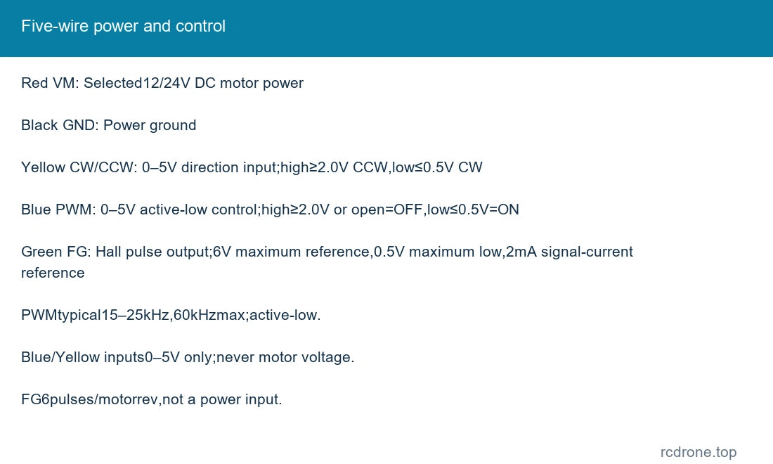
| Red | VM | Selected 12/24V DC motor power |
| Black | GND | Power ground |
| Yellow | CW/CCW | 0–5V direction input; high≥2.0V CCW, low≤0.5V CW |
| Blue | PWM | 0–5V active-low control; high≥2.0V or open=OFF, low≤0.5V=ON |
| Green | FG | Hall pulse output; 6V maximum reference, 0.5V maximum low, 2mA signal-current reference |
PWM input is 0–5 V, typically 15–25 kHz, with 60 kHz maximum frequency reference. The blue input is active-low: low enables the motor, while high or open switches it off. The yellow direction input is also 0–5 V; do not apply motor supply voltage to either control input or FG. FG provides 6 pulses per motor revolution; use a compatible counter input and actual reduction ratio for output counts.
For direct full-speed operation, the illustrated connection joins blue, black and yellow to DC negative and red to DC positive. This selects the table's low-input direction. Keep green FG isolated unless connected to suitable receiving electronics. Check actual lead colors and terminal labels before energizing.
Optional Control Board Connection
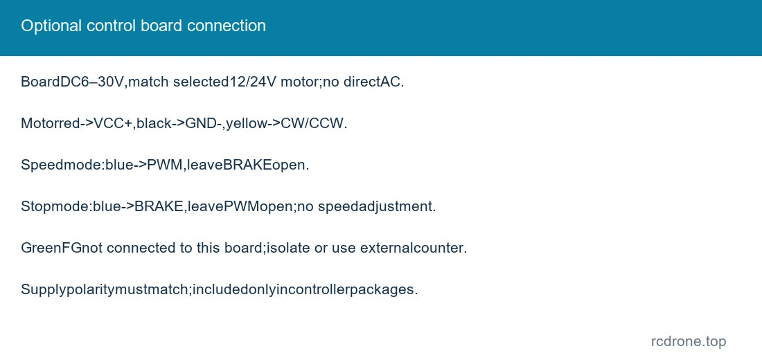
The board input is DC 6–30 V reference; use the selected motor voltage within that range. Never connect household AC. Connect motor red to motorVCC+, black to motorGND− and yellow to CW/CCW. For adjustable speed, connect blue to PWM and leave BRAKE unconnected. For the alternative stop-control connection, connect blue to BRAKE and leave PWM unconnected; speed adjustment is not available in that mode. These are alternative wiring arrangements, not simultaneous features.
The illustrated board does not measure FG speed. Leave the green FG wire isolated from the board's power, PWM and brake terminals. Match supply polarity: reversing the board supply can damage it. Only packages naming the controller include this board; controller and motor protection do not remove the need for suitable wiring, current capacity and system protection.
Mechanical Installation and Operation
Use the preserved drawing to check shaft fit, M 3 center-thread depth, mounting position and rear-connector clearance. Avoid overlong screws, shaft impacts and side loading. Guard the exposed shaft and keep debris out of the gearbox. Do not treat worm holding resistance as a safety-rated brake. Prevent prolonged overload and provide ventilation.
Applications
Compact automation, robot mechanisms, adjustment stages and instrument drives requiring right-angle geared motion and a simple DC/PWM interface. Select actual speed, torque, mounting and control behavior for the mechanism.
What's Included
One selected brushless worm gear motor. Bracket and/or brushless speed-control board are included only where named in the package, with the illustrated matching hardware. Power supply, external FG counter, complete robot and additional loose internal motor parts are not included.
FAQ
Does the motor need a separate three-phase ESC?
No. Its commutation driver is built in; use the selected DC supply and control inputs.
Does the optional board display or read FG speed?
No. Keep FG separate and use compatible external receiving electronics if speed measurement is required.
Can I use speed adjustment and stop-control wiring together?
The illustrated board uses alternative blue-wire connections: blue to PWM for speed, or blue to BRAKE for stop control without speed adjustment.
Why does the 32: 1 option have 195 FG pulses?
The detailed table uses 32.5: 1 for that nominal selector label, and 6×32.5 gives 195 pulses.
Visual Details