GepRC Pika user manual

Quickstart Manual V1.0 2018/11/01
Warning, disclaimer:
CAUTION:This radio controlled RC Quadcopter is not a toy
This product is for a radio controlled (RC) quadcopter. Improper operation,maintenance or assembly can potentially cause a RC quadcopter to pose a danger to persons or objects including but not limited to the possibility of causing serious physical injury an even death
Moving components can present a hazard to opertors,and anyone or anything that could be in the flying area of the RC Quadcopter.
Under no circumstance should a minor be allowed to operate this RC Quadcopter without the approval,monitor and direction of his parent or legal guardian who takes full responsibility for all of the minor´s actions.
This product is intended for being operated by experienced mature RC Quadcopter pilots under controlled safaty conditions and on locations properly authorized and setup for safe flying and away from other people.
Do not operate an RC Quadcopter within the vicinity of electrical power lines during inclement weather or near crowds of people
The manufacturer and/or its distributors assume no responsibility or liability whatsoever for any damages including but not limited to ones generated by incidental or consequential damages.
The operator of the RC Quadcopter assumes all responsibility and liability that result from the correct or incorrect operation of the RC Quadcopter.
Contents
- BASIC KNOWLEDGE - 7 -
- INSTALL BETAFLIGHT - 8 -
- INSTALL THE RECEIVER - 8 -
- BIND THE RECEVIER - 10 -
- SET THE RADIO - 11 -
- HOW TO UNLOCK - 13 -
- SET UP THE VTX - 13 -
- INSTALL PROPELLER - 15 -
- CONTACT US - 15 -
Summary:
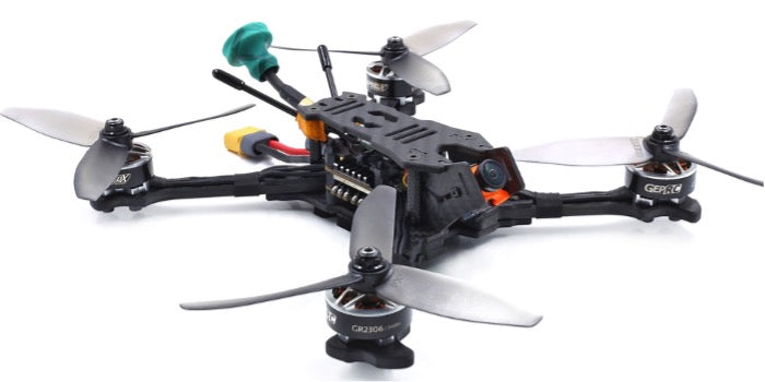
Specifications:
Model: Pika
Wheelbase: 220mm
Firmware: OMNIBUSF4SD
Input Voltage: support 2-5S Lipo
Motor:GR2306 2450kv
Propeller:GEP5040*3 (10 pairs)
Weight: 320 grams with props
Receiver: Frsky XM+ (ONLY BNF INCLUDE)
Frame: GEP-OX-H5
Carbon:Full 3K carbon fiber
Wheelbase: 220mm
Thickness of bottom plate: 3mm
Thickness of top plate: 3mm
Thickness of lens plate:2mm
Thickness of arms plate:5mm
Flight Controller: SPAN F4 Tower AIO
MCU: STM32F405
MPU: MPU6000
ESC: 40A * 4 BLHeli_s (Dshot 150/300/600) support 2~5S LiPo
VTX:5.8GHz (48 Channel) (OFF/25/200/600mW)
Features:
- All 3k carbon plate
- Use the most stable SPAN F4 Tower AIO
- 40A 4IN1 BLHeli_S DSHOT600 ESC
- F4 Flight controller
- Frsky XM+ receiver
- Integrated OSD to clearly see the flight voltage and current
- 8ghz VTX Pit/25/200/600mw 48ch
- Runcam Swift mini 2 Camera
- GR2306 2450kv motors and high efficiency 5040 propeller
- It came with two RHCP pagoda II antennas
- Factory frequency can fly
Important tip: before commissioning, please remove the propeller
1、 Basic knowledge
- The PIka is a 5 inch propeller drone. This is not a toy. If done incorrectly, it can harm the human body.
- The PIka is using the Betaflight firmware flight control, and the introduction of Betaflight can be referred to the second part.
- The way to type the rudder, as shown below:
n
- The order and direction of the motor:
- The manufacturer recommends a 4s 1500mAh battery flight , but can also fly with the 4s (1300mAh- 1500mAh).
- PIka does not recommend flying in crowded places to avoid hurting people.
- if you want to feel FPV (first person vision), please flying with video glasses.
2、 Install Betaflight
- Betaflight is an open source flight control procedures, specific introduction can refer to website: https://github.com/betaflight
- for the firmware required by PIka, please click the following link to download the firmware name: 2.5_OMNIBUSF4SD.hex
- Latest version of firmware download website:https://github.com/betaflight/betaflight/releases
- Be sure to download the 2.5_OMNIBUSF4SD.hex version. (You can select the latest version)
- Install driver and ground station Betaflight n https://github.com/betaflight/betaflight/wiki/Installing-Betaflight n Ground station Betaflight - Configurator download address (you need to install Chrome browser) :
u https://chrome.google.com/webstore/detail/betaflight-configurator/kdaghagfopacdngbohiknlhcocjccjao/re views 3、 Install the Receiver
- If you choose the BNF version, you can Bind use the frequency and do not need to install the receiver again.
- if you choose the PNP version, you will need to install the receiver on your own, Please click the following steps to connect (such as the Frsky r-xsr receiver) :
- note:must dismantle propeller for debugging.
- Open the screws of the PIka, open the top vtx board, and you can see the flight control board on the second floor.
- The flight control board will have three welding locations: 5V,GND,S.Bus, Welding in the corresponding position n Finally, fix the receiver and lock the corresponding screw n As shown in the picture below:
4、 Bind the Recevier
- Each manufacturer's receiver is not identical to the frequency, now take the r-xsr receiver of Frsky as an example.
Other manufacturers' receivers please refer to the corresponding manufacturer's frequency information.
n 1:Power on X9D —— Short press MENU —— Press PAGE turn to second page(such as below picture)
n 2:Move the cursor to the "Mode" option,"Mode" option the working mode of XJT can be switched. There are three types of D16, D8, and LR12 respectively. Please select according to your receiver:
System :Compatible receiver
D16 :X8R, X6R, X4R, XSR and other X series receivers
D8: D8R, D4R and other D series receiver, V series ii receiver and X8R, X6R D8 mode
LR12: L9R receiver n 3:Move the cursor to the "Bind" option, and click ENTER. "Bind" is in a scintillating state and is entering the bind the receiver state
Bind order:
Press F/S button(The Receiver) —— Put through power supply —— The light of the receiver green, red light flash——Press ENTER at Frsky X9D “Bind”—— Unplug the power and rewire (he light of the receiver green, red light flash, That’s ok)。
5、 Set the Radio
- You need to set the radio so that you can control the Drone.
- This is use MODE2 n Create a new MODE2 model n Then open the necessary channels to the remote control (please see picture below)
|
Channel |
Function |
operation |
|
Channel 5(2 switch) |
Unlock |
0 unlock , 1 lock |
|
Channel 6(3 switch) |
Control Drone posture |
0 Rate , 1 Angle , 2 Horizon |
|
Channel 7(2 switch) |
Control Buzzer |
0 Buzzer on,1 Buzzer off |
Set up as picture below:
6、 How to unlock
Note: when the test motor turns, the propeller must be unloaded
- Unlock type n The throttle to the minimum
n Knock down 5 channels to unlock
7、 Set up the VTX
- Set the Channel. In standby mode, press and hold the key for 3 seconds, the blue LED flashes, short press, change the channel value.Every time 1 press will change the CH, followed by 1CH to 8CH cycles.
- Set the Band. In the channel setting mode, press and hold the key for 3 seconds, the green LED flashes, briefly presses, changes the frequency group value.Every time 1 press will change the band, and then the A band to F band loop.
- Set the Power.In the band setting mode, press and hold the key for 3 seconds, the red LED flashes, short press, change the output power value.Every time 1 press will change the power, followed by
25mW / 100mW / 600mW cycle.
- frequency table:
|
|
CH1 |
CH2 |
CH3 |
CH4 |
CH5 |
CH6 |
CH7 |
CH8 |
|
Band A |
5865 |
5845 |
5825 |
5805 |
5785 |
5765 |
5745 |
5725 |
|
Band B |
5733 |
5752 |
5771 |
5790 |
5809 |
5828 |
5847 |
5866 |
|
Band E |
5705 |
5685 |
5665 |
5645 |
5885 |
5905 |
5925 |
5945 |
|
Band F |
5740 |
5760 |
5780 |
5800 |
5820 |
5840 |
5860 |
5880 |
|
Band R |
5658 |
5695 |
5732 |
5769 |
5806 |
5843 |
5880 |
5917 |
|
Band H |
5362 |
5399 |
5436 |
5473 |
5510 |
5547 |
5584 |
5621 |
-
VTX LED display
- BLUE: Frequency channel display, the time of flash represents 1 to 8 channels, 1 = CH1,2 = CH2, ... 8 = CH8.
- GREE: Frequency Band display, the number of flashes represents the frequency group from A to R, 1=A, 2=B……6=H
- RED: Power output display, 1 = 25mW, 2 = 100mW, 3 = 600mW.
How to turn VTX on or off: In the working state, quickly double-click the set button, RED / GREEN / BLUE sync flash, VTX can be turned off, and also quickly double-click of the key to turn on the VTX output.
8、 Install Propeller
- The propeller is divided into two types: Left and Right.
- Install as shown. Notice the positive and negative directions